
Introduction:
Reflection gratings offer substantial advantages over transmission gratings for pulse compression, such as the high diffraction efficiency of multilayer dielectric (MLD) gratings and the broad spectral and angular bandwidth of gold gratings. However, reflection gratings have one major disadvantage: there must be an appreciable non-zero angle, called the beam deviation angle, between the incident and diffracted beams. This restriction precludes operation exactly at the Littrow angle, which often provides the best grating performance in terms of efficiency and bandwidth.
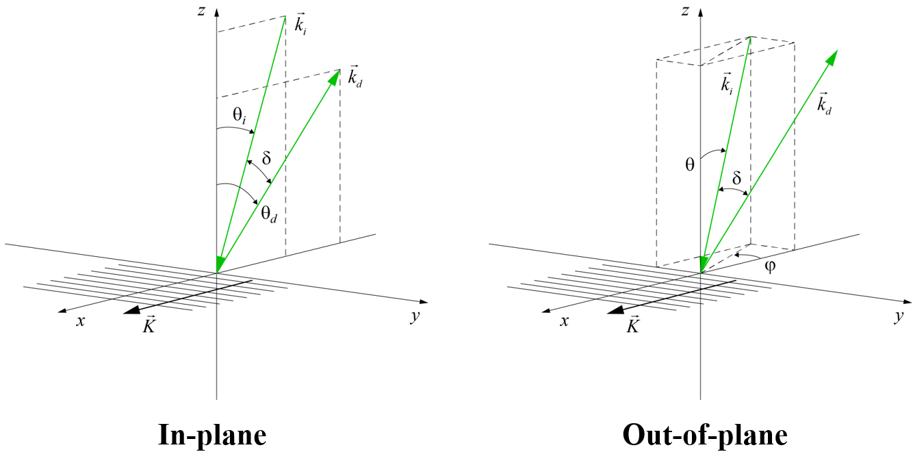
Typically the beam deviation angle is achieved by choosing a non-Littrow angle of incidence, while keeping the incident beam within the grating plane, defined to be the plane perpendicular to both the grating lines and the substrate surface. This so-called “in-plane” configuration is shown in Fig. 1, where ki is the wavevector describing the incident beam direction, kd is the diffracted wavevector, and δ is the beam deviation angle in the grating plane (x-z plane). But some gratings suffer rapid performance degradation for angles even a few degrees away from the Littrow angle. As an alternative, gratings may also be used in the “out-of-plane” configuration, also shown in Fig. 1. Advantageously, the incident beam can be chosen to exactly meet the out-of-plane Littrow condition, such that the incident and diffracted beams are symmetrically positioned on either side of the grating plane.
In this technical note we show how to both understand and correctly calculate the performance of pulse compression gratings used in the out-of-plane configuration. Examples of both gold and MLD gratings are given, with both lower and higher dispersion. These reveal how large of a deviation angle is possible for common situations, and demonstrate how critical it is to select the optimal polarization orientation.
Advantages of the out-of-plane configuration:
Often system designers avoid the out-of-plane configuration because of its perceived complexity and inconvenience when it comes to mounting and alignment. Yet there are many cases for which out-of-plane use provides substantial system flexibility and/or performance boost. Most often the advantage is related to improved angular performance. A certain combination of grating line density and wavelength chosen for temporal dispersion requirements might have very limited angular bandwidth when used in the in-plane configuration, but plenty of angular bandwidth used out-of-plane. As an example, MLD grating line densities tend to be limited in practice to those with a wavelength-to-period ratio of about 1.8, such as 1760 lines/mm for 1030 nm lasers, since this combination affords a broad in-plane angular bandwidth. But if out-of-plane use is permitted, MLD gratings with just about any line density from about 1200 to 1900 l/mm could be chosen for 1030 nm lasers.
Even for line density-wavelength combinations which permit in-plane beam deviations of up to say 10°, when beam size is large and space is limited or the temporal dispersion required is low, such that the grating separation cannot be too large, MLD gratings operated out-of-plane can offer beam deviation angles of up to 30° or more. Gold gratings also suffer from limited in-plane angular bandwidth at higher Littrow angles. For example, when high dispersion is required, such as > 1800 l/mm for 800 nm lasers, the angular bandwidth becomes quite small and can be significantly increased by using the out-of-plane configuration.
Another advantage offered by the out-of-plane configuration is increased spectral bandwidth. An example is the use of MLD gratings for compressing 800 nm Ti:Sapphire laser pulses as short as 10’s of fs [1,2]. The broadest spectral performance, required to accommodate the shortest pulses, occurs for lower-line-density gratings, such as 1480 l/mm. But these gratings have extremely narrow in-plane angular bandwidth, so must be used at the Littrow angle, and therefore can only be used out-of-plane. Even the most common 1480 l/mm gold gratings for 800 nm laser systems suffer some decrease in bandwidth due to a broad resonance on the short-wavelength side of the efficiency spectrum associated with surface plasmon coupling. By using these gratings out-of-plane, the resonance is shifted and the bandwidth is increased substantially.
For some applications the out-of-plane configuration is the only option. For example, when MLD gratings are used for spectral beam combining of high-power fiber lasers to achieve power scaling, such as in directed energy applications, there is a substantial in-plane angular range required to accommodate the input beams, so the only way to efficiently extract the output beam is by operating out-of-plane.
Out-of-plane wavevector and polarization angles:
Here we describe how to understand and measure angles associated with beam directions and polarization orientations for out-of-plane gratings. We limit the discussion to the case where the wavevectors satisfy the out-of-plane Littrow condition, in which the x-components of the incident and diffracted wavevectors are equal and opposite in direction. This is the most practically interesting case.
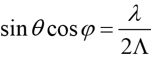
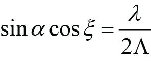
For a given combination of wavelength and grating line density, there is a single in-plane Littrow angle θL for the –1 diffracted order given by [3]
 , (1)
, (1)
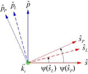
where λ is the wavelength and Λ is the grating period. Alternatively, there is an infinite number of out-of-plane incident wavevector directions which satisfy the Littrow condition, depending on how far away from the grating plane the incident beam is. In every case the diffracted beam is symmetrically positioned on the opposite side of the grating plane. There are multiple methods to label these beam directions. Here we follow Kalinchenko, et al [4] for two methods, and Wei, et al [5] and Alessi, et al [1] for the third method, albeit with different variable names. Each method is associated with a certain rotation to obtain the incident beam position. This approach results in a different orientation of the electric field polarization vectors for each of the three methods.
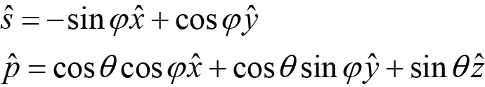
The three methods are called Roll, Pitch, and Lab, and are illustrated in Fig. 2. We begin by assuming the incident wavevector ki lies in the grating (x-z) plane, with a given polarization (s parallel to the y direction or p parallel to the x-z plane). The wavevector is moved out-of-plane by rotating ki by some angle about an axis which is different for each method.
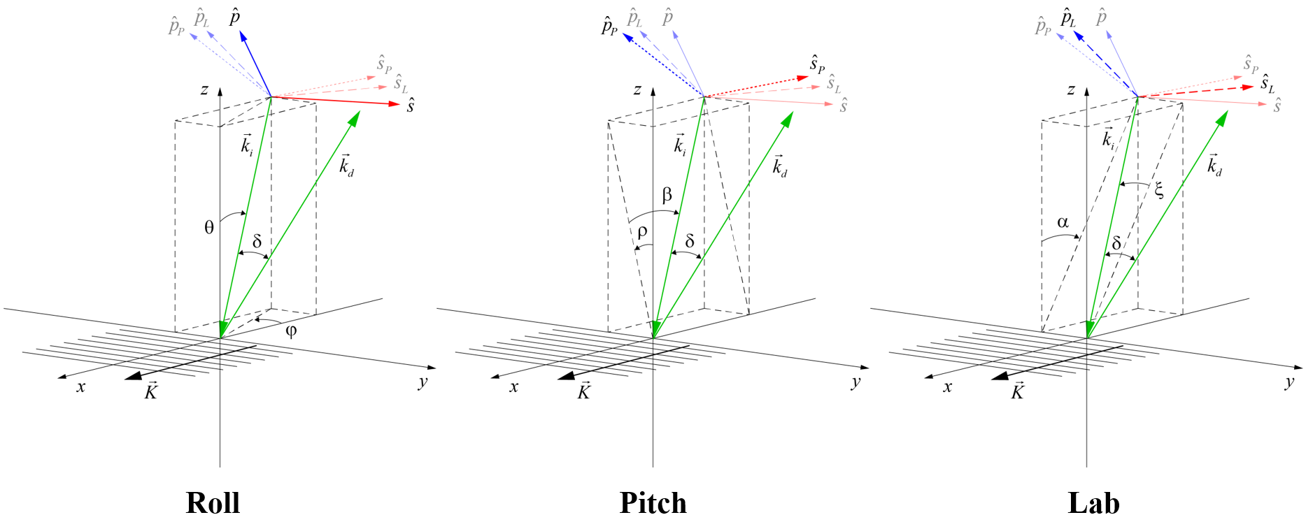
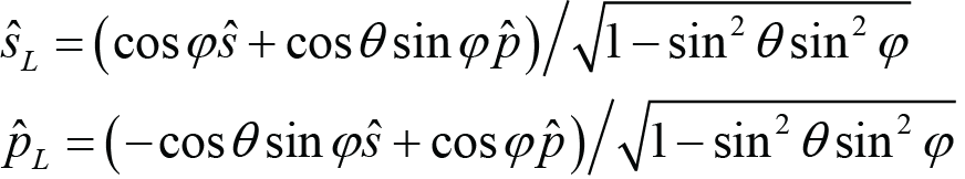
For the Roll method, the incident beam starts in the grating plane at an angle θ relative to the z axis, and then is rotated (rolled) about the z axis by an angle φ. This is the only method for which the initial s- and p-polarization orientations remain s- and p-polarized after the rotation, based on the definitions that s-polarized light is perpendicular to the plane of incidence (i.e., the plane containing ki and the z axis) and p-polarized light is parallel to the plane of incidence. This is why the polarization unit vectors resulting from Roll are labeled simply s and p in the diagrams, with no subscript.
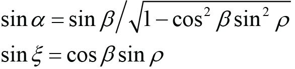
For the Pitch method, the incident beam starts in the grating plane at an angle β relative to the z axis, and then is rotated about the x axis by an angle ρ. After pitching, light which was initially s- or p-polarized is now oriented in the directions sP or pP, respectively.
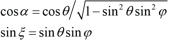
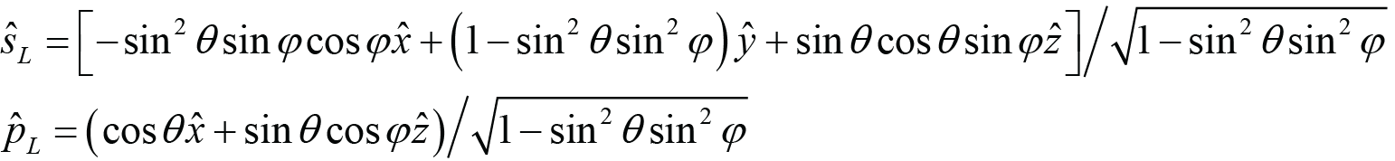
For the Lab method, the incident beam starts in the grating plane at an angle α relative to the z axis, and then is rotated by an angle ξ about the axis which is normal to the plane containing ki and the y axis. After rotation, light which was initially s- or p-polarized is now oriented in the directions sL or pL, respectively. This is a convenient method to label the angles, since the beam deviation angle is simply twice the rotation angle, or δ = 2ξ. The reason we call it the Lab method is that it most closely describes how some labs have chosen to mount and align out-of-plane gratings to date [6]. Commonly in-plane compressors are designed with all beams lying in a horizontal plane relative to the lab frame of reference. The same layout can be achieved using out-of-plane gratings by choosing the horizontal plane to be the plane containing ki and the y axis. In this case the direction sL is parallel to this horizontal plane and the direction pL is perpendicular to this plane, i.e., vertical.
The incident and diffracted (at Littrow) wavevectors in terms of the angles for each method are as follows:
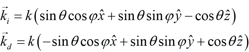 (Roll), (2)
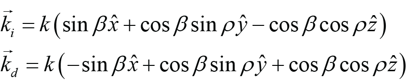 (Pitch), (3)
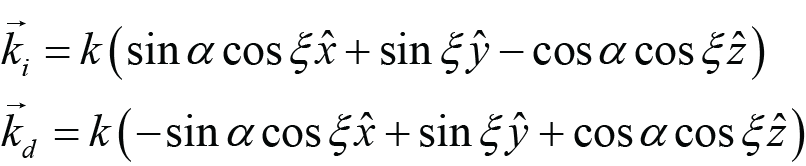 (Lab), (4)
where the magnitude of the wavevector is k = 2π/λ. The angles which correspond to the Littrow condition for each of the methods are as follows:
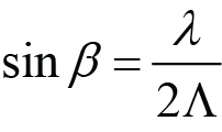
 (Roll Littrow), (5)
 (Pitch Littrow), (6)
 (Lab Littrow). (7)
Notice that for the Roll and Lab methods, the inclination angles analogous to the in-plane Littrow angle (θ and α, respectively) are different for different rotation angles φ and ξ. So as the grating is rotated, the inclination angles must also be adjusted to maintain the Littrow condition. For the Pitch method, Littrow is maintained as the grating is rotated (pitched).
The different rotations associated with the three methods result in different orientations of the polarization unit vectors, as shown in Fig. 3. These unit vectors are always perpendicular to ki. Notice that in practice we need not be restricted to these polarization orientations; we may choose any polarization orientation once a desired ki is achieved, regardless of how it is achieved. For a given ki the highest diffraction efficiency at a certain wavelength or the broadest angular or spectral bandwidth might be achieved with a polarization orientation that is not aligned with any of those shown in Fig. 3. The angle ψ in this diagram measures the rotation of the polarization orientation relative to true s-polarization, which is always parallel to the x-y plane and perpendicular to the plane of incidence.
The polarization orientations shown in Fig. 3 are as follows:
 (Roll), (8)
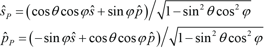 (Pitch), (9)
 (Lab). (10)
Here we have chosen to write these in terms of the angles θ and φ associated with the Roll method, although we could have chosen any of the sets of angles. It is straightforward to convert between the angles of one method and those of another (see Appendix A).
Using Eqs. (8) – (10) it is possible to explicitly write the polarization rotation angles ψ as follows. Note that for θ, φ < 90°, it is evident from the construction of Eqs. (11) and (12) that ψ(p) = ψ(s) + 90. That is, all of the angles ψ are measured relative to the s-polarization axis.
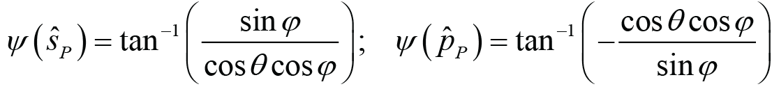 ; (11)
 . (12)
With these angles defined, it is now possible to consider out-of-plane grating designs and compare the performance of these to that of the more common in-plane designs. Perhaps most interesting is to explore the dependence of the diffraction efficiency on the beam deviation angle δ. For a given combination of wavelength and grating line density, the wavevector angles α and ξ which satisfy the out-of-plane Littrow condition can be found from ξ = δ/2 and Eq. (7). The angles θ and φ may then be obtained from Eq. (A.2). The polarization orientations are then determined by Eqs. (8) – (12). In the following sections we examine a number of different grating designs which are representative of those found in the most commonly used compressor configurations.
Gold grating with 1480 lines/mm at 800 nm:
As noted above, lower dispersion gold gratings such as those commonly used with Ti:Sapphire-based chirped-pulse-amplification lasers already exhibit quite broad spectral and angular diffraction efficiency performance. So we don’t expect a significant performance improvement by utilizing out-of-plane gratings. Nevertheless, in this example we see there is some improvement which could be beneficial for certain systems, especially those with very short pulses that require bandwidths of up to 200 nm or more. This example also serves to illustrate how important it is to select the proper polarization orientation to achieve maximum efficiency for an out-of-plane configuration.
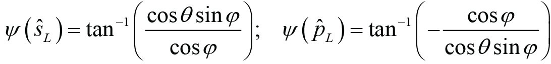
Fig. 4(left) shows the diffraction efficiency at 800 nm over a range of beam deviation angles for a standard gold grating design, calculated using Rigorous Coupled Wave Analysis (RCWA) [7]. All results are at the Littrow condition, and therefore the inclination angle θ is adjusted for each rotation angle φ. Four of the five curves correspond to different p-polarization orientations. The Roll, Pitch, and Lab orientations are the unit vectors p, pP, and pL, respectively, described above. Optimal is simply the orientation which gives the maximum efficiency. The fifth curve is the diffraction efficiency obtained using an in-plane configuration with p-polarization. On this plot the Optimal and Lab efficiencies are indistinguishable, since the corresponding polarization orientations are almost identical.
Fig. 4(right) shows the diffraction efficiency for a beam deviation angle of δ = 30° as a function of the polarization orientation angle ψ. There is a sinusoidal dependence. The polarization orientations which result when we start with s- or p-polarized light and perform the rotation associated with each method are highlighted as solid markers. Using the Roll method always results in s- and p-polarization orientations of ψ = 0° and 90°, respectively, by definition. For this case the Lab polarization angle ψ(pL) = 108.45° and the Optimal angle ψ = 108.17° are almost identical, as noted above. Clearly, when using a 1480 l/mm gold grating out-of-plane in a Ti:Sapphire laser system the Lab method should be used to orient the polarization. That is, the light should be polarized vertically when the grating is mounted such that the plane containing the incident wavevector and the y axis is horizontal.
Fig. 5 shows the spectral dependence of the diffraction efficiency at beam deviation angles of δ = 10° (left) and δ = 30° (right). As in Fig. 4 the Optimal and Lab efficiencies are indistinguishable. Also as observed in Fig. 4 at 800 nm, the Optimal and Lab polarization orientations result in the highest efficiency over the full spectral range, followed by the Pitch and then Roll orientations. Comparing the out-of-plane efficiency using the Optimal or Lab polarization to the in-plane efficiency, the most notable difference derives from the surface-plasmon coupling resonance which decreases the efficiency at shorter wavelengths. While the difference at a 10° beam deviation angle is very small, for a 30° beam deviation the spectral response for the out-of-plane configuration is about 25 nm wider than that of the in-plane configuration. This is because the resonance shifts toward longer wavelengths for larger in-plane beam deviation angles, but toward shorter wavelengths for larger out-of-plane angles.
MLD grating with 1480 lines/mm at 800 nm:
High-average-power (HAP) petawatt-class lasers are becoming increasingly popular, especially for practical applications. Gold pulse compression gratings have been the standard for fs-pulse-duration Ti:Sapphire lasers, but thermal expansion of gratings caused by absorbed heat from a HAP laser beam causes wavefront deformation, which both affects beam focus and degrades pulse temporal characteristics. MLD gratings appear to be an obvious alternative for HAP lasers due to their extremely low absorption. Yet the sensitive role optical interference plays in these gratings leads to a limited range of dispersion values that yield broad spectral and angular bandwidth solutions for a given wavelength. For the desired more moderate dispersion values, MLD gratings must be operated at the Littrow angle, thus requiring an out-of-plane configuration. This example illustrates how well these gratings can perform in the out-of-plane Littrow configuration, as well as the polarization orientation which yields maximum efficiency.
Fig. 6(left) shows the diffraction efficiency at 800 nm over a range of beam deviation angles for an MLD grating design optimized for high efficiency at substantial beam deviation angles and broad spectral performance. The efficiency is calculated using Rigorous Coupled Wave Analysis (RCWA) [7]. All results are at the Littrow condition, and therefore the inclination angle θ is adjusted for each rotation angle φ. Four of the five curves correspond to different s-polarization orientations. The Roll, Pitch, and Lab orientations are the unit vectors s, sP, and sL, respectively, described above. Optimal is simply the orientation which gives the maximum efficiency. The Optimal, Pitch, and Lab efficiencies are all very similar. The fifth curve is the diffraction efficiency obtained using an in-plane configuration with s-polarization. As expected, the in-plane angular bandwidth is poor.
Fig. 6(right) shows the diffraction efficiency for a beam deviation angle of δ = 30° as a function of the polarization orientation angle ψ. There is a sinusoidal dependence, though for this grating the modulation of the efficiency is weaker than for the gold grating example above, since there is appreciable efficiency for the non-optimal (in this case p) polarization. Both the Lab and Pitch polarization orientations result in nearly optimal diffraction efficiency. To achieve the Lab polarization, the light should be polarized horizontally when the grating is mounted such that the plane containing the incident wavevector and the y axis is horizontal. The Pitch polarization is achieved when the grating is initially aligned with s-polarization in-plane, and then rotated (pitched) about the grating wavevector K.
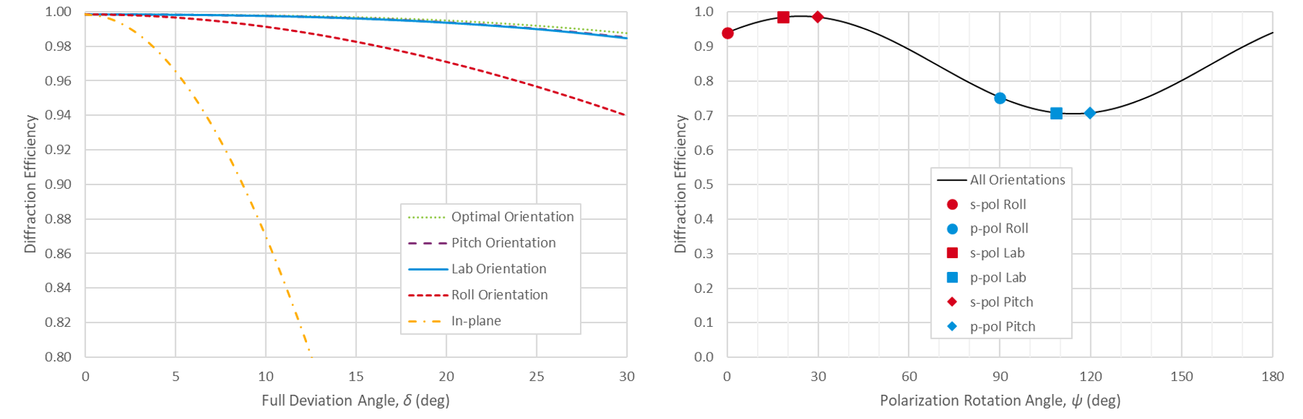
Fig. 7 shows the spectral dependence of the diffraction efficiency at beam deviation angles of δ = 10° (left) and δ = 30° (right). At 10° the Optimal, Pitch, and Lab efficiencies are nearly identical, and are better than that achieved with Roll and far superior to the best in-plane efficiency. At 30° the Lab orientation becomes slightly inferior to the Optimal and Pitch orientations. Interestingly, the Pitch orientation has an even broader spectral response than the Optimal orientation, which is only guaranteed to be optimal at the 800 nm center wavelength. In-plane use with a 30° beam deviation angle is not feasible at all.
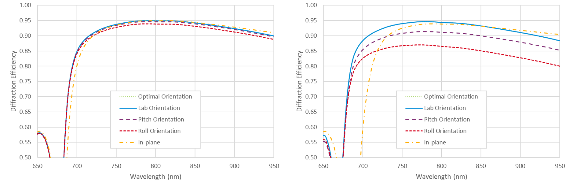
Gold grating with 1760 lines/mm at 1030 nm:
Lower-dispersion gold gratings such as the popular 1480 lines/mm at 800 nm combination, which has a wavelength-to-period ratio of about 1.2 and a Littrow angle of 36°, naturally exhibit quite broad spectral and angular bandwidth. When higher dispersion is required to achieve greater pulse compression or a more compact compressor, the angular bandwidth of gold gratings used in-plane becomes limited. Use of the out-of-plane configuration can overcome this limitation. For this example we examine a 1760 lines/mm grating at 1030 nm, which has a wavelength-to-period ratio of about 1.8 and a Littrow angle of 65°.
Fig. 8(left) shows the diffraction efficiency at 1030 nm over a range of beam deviation angles for a standard gold grating design. The Roll, Pitch, and Lab orientations are the unit vectors p, pP, and pL, respectively, described above. Optimal is simply the orientation which gives the maximum efficiency. The fifth curve is the efficiency obtained using an in-plane configuration with p-polarization. As expected the in-plane performance degrades quickly with increasing beam deviation. On this plot the Optimal and Lab efficiencies are indistinguishable, since the corresponding polarization orientations are almost identical.
Fig. 8(right) shows the diffraction efficiency for a beam deviation angle of δ = 30° as a function of the polarization orientation angle ψ. For this case the Lab polarization angle ψ(pL) = 95.45° and the Optimal angle ψ = 95.63° are almost identical, as noted above. Comparing these results to those of the 1480 l/mm at 800 nm combination in Fig. 4, we see that in both cases the Optimal and Lab polarization orientations experience less than 1% degradation even as the out-of-plane beam deviation angle increases to 30°. However, for the lower-dispersion 1480 l/mm case the Pitch orientation performs reasonably well, and the Roll orientation is worse, whereas for the higher-dispersion 1760 l/mm case the Roll orientation is almost as good as the Optimal and Lab orientations, while the Pitch orientation is as poor as the narrow-bandwidth in-plane result.
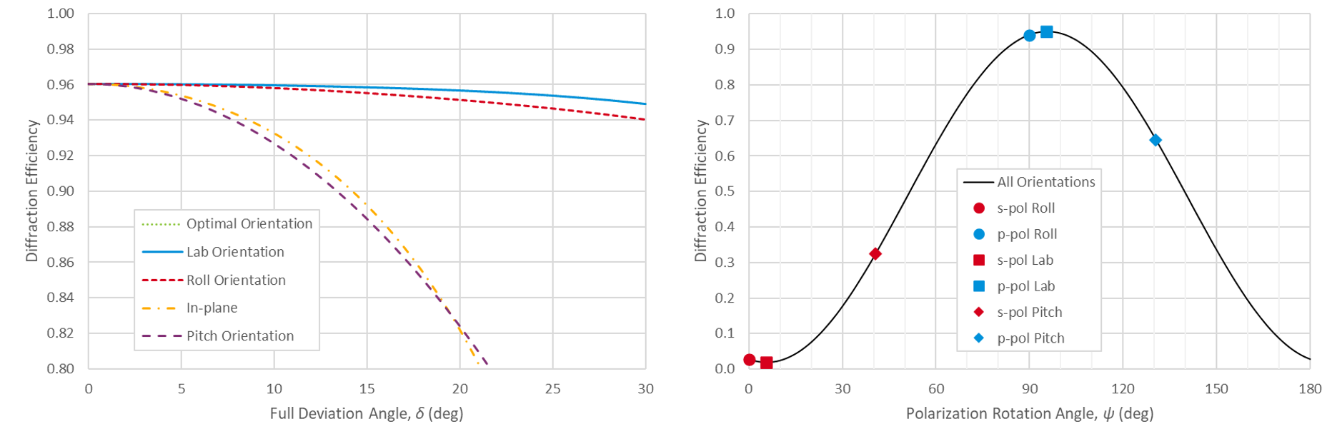
Fig. 9 shows the spectral dependence of the diffraction efficiency at beam deviation angles of δ = 10° (left) and δ = 30° (right). As in Fig. 8 the Optimal and Lab efficiencies are indistinguishable. The Optimal and Lab polarization orientations result in the highest efficiency over the full spectral range, followed closely by the Roll orientation. The Pitch orientation is appreciably worse at 10°, and unacceptably low at 30°. The in-plane performance demonstrates substantially more bandwidth at longer wavelengths at 10°, but is simply too low at 30°.
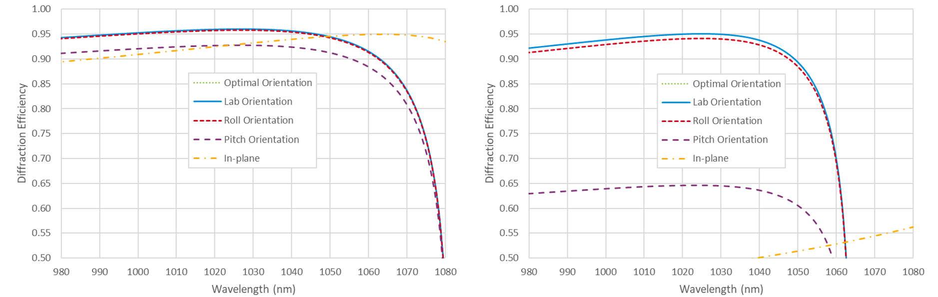
These plots demonstrate an important consideration for out-of-plane use when the wavelength-to-period ratio or Littrow angle are high. Clearly the spectral bandwidth is limited by the severe drop in efficiency at longer wavelengths. The drop results from the cutoff wavelength beyond which no –1 order diffraction occurs, and this wavelength decreases with increasing out-of-plane angle even as the Littrow condition is maintained. For in-plane incidence the cutoff wavelength at angle θ for a grating of period Λ is λcutoff = (1 + sinθ)Λ. So for a 1760 l/mm grating (Λ = 568 nm) the in-plane incidence angles to achieve a 10° beam deviation are 70.5° and 60.5°, and the corresponding cutoff wavelengths are 1103 nm and 1063 nm, respectively. The in-plane incidence angles to achieve a 30° beam deviation are 84.8° and 54.8°, and the corresponding cutoff wavelengths are 1134 nm and 1032 nm, respectively. It can be shown for out-of-plane incidence the cutoff wavelength is given by
 , (13)
which reduces to the simpler in-plane equation for φ = δ = 0. The cutoff wavelengths at Littrow incidence for δ = 10° and 30° are 1081 and 1064 nm, respectively, demonstrating the decreasing wavelength with increasing beam deviation angle as seen in the plots in Fig. 9.
MLD grating with 1760 lines/mm at 1030 nm:
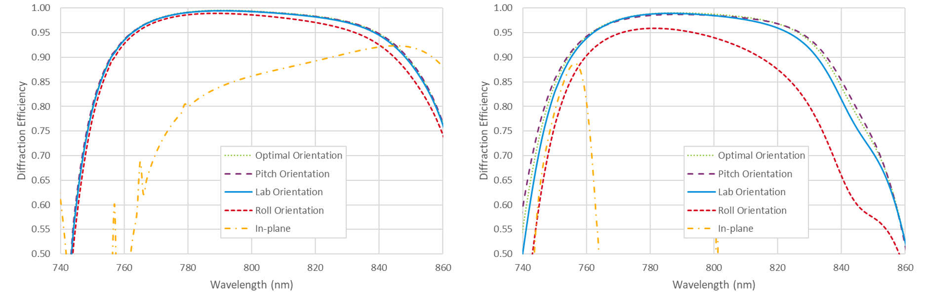
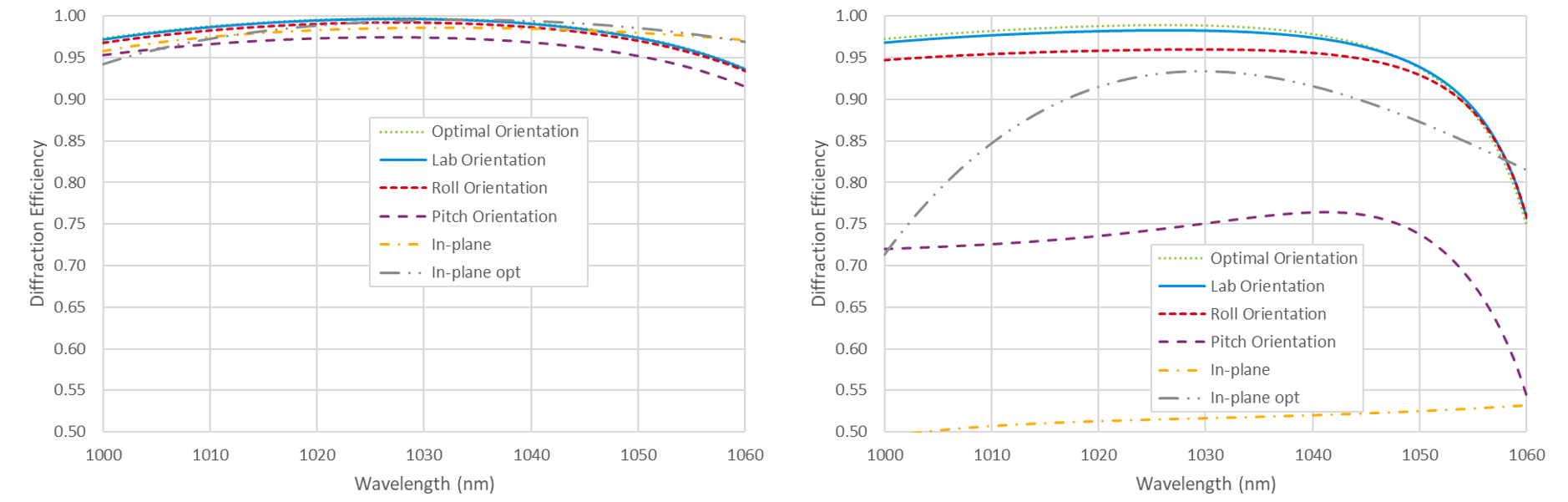
For this example we consider the popular 1760 lines/mm MLD grating, which is commonly used for 1030 nm Yb-based laser systems. This grating line density is chosen mainly because the wavelength-to-period ratio gives rise to quite broad in-plane angular bandwidth in MLD gratings, thus enabling practical compressor implementation. Below we find that using an out-of-plane configuration offers equivalent performance for moderate beam deviation angles of about 10°, but more importantly, makes it possible to build compressors with much larger deviation angles, even up to 30° and higher.
Fig. 10 shows the diffraction efficiency at 1030 nm over a range of beam deviation angles for two MLD grating designs. The design on the left is optimized for small beam deviation angles, while the design on the right is optimized for a beam deviation of δ = 30°. The Roll, Pitch, and Lab orientations are the unit vectors s, sP, and sL, respectively, described above. Optimal is simply the orientation which gives the maximum efficiency. The fifth curve is the diffraction efficiency obtained using an in-plane configuration with s-polarization. Like the 1760 l/mm 1030 nm gold grating example above, the Lab polarization orientation performs almost as well as the Optimal orientation, the Roll orientation is only moderately worse, and the Pitch orientation is far inferior. Note that this in-plane performance is considered excellent in terms of angular bandwidth for MLD gratings. The most striking feature of these results is that the MLD design on the right achieves nearly 99% diffraction efficiency for linearly polarized light with a full beam deviation angle of δ = 30°!

Fig. 11 shows the diffraction efficiency for beam deviation angles of δ = 10° (left) and δ = 30° (right) as a function of the polarization orientation angle ψ. Unlike the 1760 l/mm gold grating example above, there is a noticeable difference between the Lab polarization orientation and the Optimal orientation, so designers looking for the best possible efficiency and therefore compressor throughput should consider polarization rotation in the compressor design. Comparing these results to those of the 1480 l/mm MLD grating at 800 nm in Fig. 6, we see that in both cases the Optimal and Lab polarization orientations experience about 1% degradation even as the out-of-plane beam deviation angle increases to 30°. However, for the lower-dispersion 1480 l/mm case the Pitch orientation performs reasonably well, and the Roll orientation is worse, whereas for the higher-dispersion 1760 l/mm case the Roll orientation is within a few % of the Optimal and Lab orientations, while the Pitch orientation is as poor as the in-plane result.
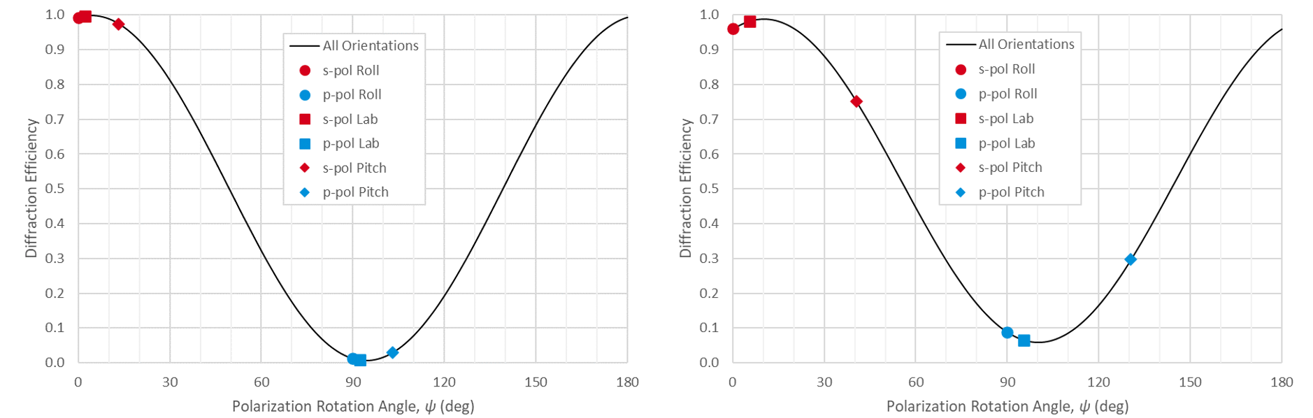
Fig. 12 shows the spectral dependence of the diffraction efficiency at beam deviation angles of δ = 10° (left) and δ = 30° (right). The Optimal and Lab polarization orientations result in the highest efficiency over the full spectral range, followed closely by the Roll orientation. The Pitch orientation is appreciably worse at 10°, and unacceptably low at 30°. Two in-plane results are shown for each beam deviation angle. The one labeled just “In-plane” shows the efficiency obtained with the same design as used for the out-of-plane results, while the one labeled “In-plane opt” is a different grating design specifically optimized for the best in-plane performance at the targeted beam deviation angle. For all other examples above, the improvement associated with a more carefully optimized in-plane design is not significant, so results are shown with only the out-of-plane designs. The in-plane performance is very comparable to the best out-of-plane results for 10°, but is simply too low at 30°, even for the optimized version. As explained above for the 1760 l/mm gold grating example, the drop in efficiency at longer wavelengths is due to the cutoff wavelength effect, and is worse for increasingly out-of-plane angles at the Littrow condition.
Discussion of results:
The results from the four examples above are summarized in Table 1. Here the “+”, “±”, and “–” symbols qualitatively indicate excellent, moderate, and poor performance, respectively.
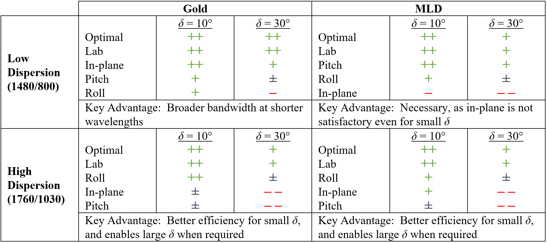
In every case excellent performance can be realized for beam deviation angles up to 30° using either the Lab polarization orientation, or the Optimal orientation which is just slightly better in the case of MLD gratings. Care should be taken to avoid the Roll orientation for low-dispersion gratings, and the Pitch orientation for high-dispersion gratings.
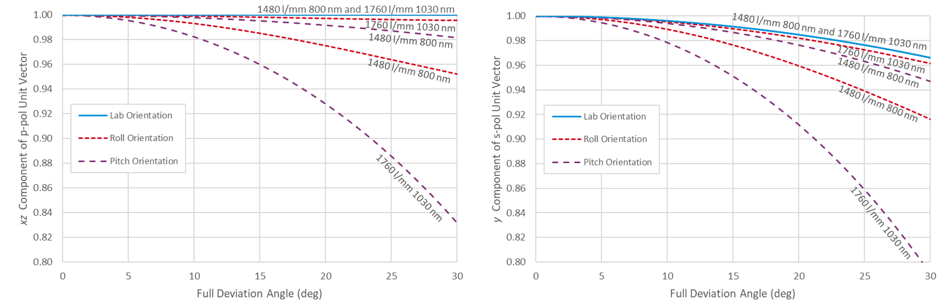
The key to understanding these results lies in the polarization orientation. While an oversimplification, a reasonable explanation is that gratings which perform optimally for p-polarized light in-plane should perform best out-of-plane when the x-z component of the electric field vector remains high and the y component is negligible, such that the light is polarized as perpendicular to the grating lines as possible. In Fig. 13(left) the x-z components of the p-polarization unit vectors p, pP, and pL for the Roll, Pitch, and Lab orientations, respectively, are plotted as a function of deviation angle. It is evident that the Lab component remains high for the full range of deviation angles regardless of the grating dispersion. This component also remains somewhat high in the Roll orientation for high-dispersion gratings and the Pitch orientation for low-dispersion gratings. The x-z component degrades quickly with deviation angle in the Pitch orientation for high-dispersion gratings and the Roll orientation for low-dispersion gratings. This behavior is consistent with efficiency results observed for gold gratings above.
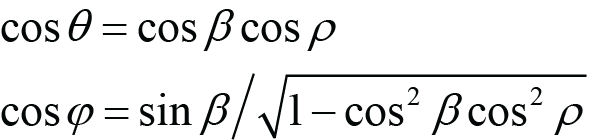
In an analogous fashion, gratings which perform optimally for s-polarized light in-plane should perform best out-of-plane when the y component of the electric field vector remains high and x-z component is negligible, such that the light is polarized as parallel to the grating lines as possible. Fig. 13(right) shows the y components of the s-polarization unit vectors s, sP, and sL for the Roll, Pitch, and Lab orientations, respectively. Again the behavior is consistent with the efficiency results observed for MLD gratings above.
It is worth noting an additional consideration when designing a compressor using the out-of-plane configuration. The reason this configuration is sometimes referred to as a “conical mount” of the grating is that the diffracted wavevectors associated with wavelengths other than the central (here Littrow) wavelength lie on a cone, in contrast to the in-plane diffracted wavevectors which lie in a plane [5]. It was pointed out above that a convenient out-of-plane compressor geometry positions all of the beams in a horizontal plane, just like an in-plane four-grating compressor [6]. For the out-of-plane case, the gratings are mounted with the lines parallel to this horizontal plane, which contains the incident and diffracted wavevectors and the y axis; see Fig. 1(right). However, unlike the in-plane compressor, in which wavevectors for all wavelengths lie in this plane, for the out-of-plane compressor the wavevectors are no longer parallel to the horizontal plane due to conical diffraction. One might be concerned that this behavior could lead to additional spatial and therefore also temporal dispersion. Fortunately, due to the symmetry of the four-grating compressor, the out-of-plane spatial chirp caused by the first pair of gratings is undone by the second pair, so there are no such deleterious effects.
Nevertheless, care should be taken when designing two- and one-grating compressors, which often use fold mirrors to translate the beam and return it to a different part of the grating(s). In order for the third and fourth grating reflections to undo any spatial dispersion from the first two reflections, when the beam is translated in the direction parallel to the grating lines it must experience an odd number of fold-mirror bounces. If a normal two-bounce roof-mirror assembly is used, as is commonplace for in-plane compressors, there can be significant spatial dispersion at the output of the compressor. An odd number of bounces may be achieved with a single mirror and a slight deviation angle [6], or by arranging three mirrors in a pentaprism-like assembly [8].
In conclusion, designers of grating compressors for chirped-pulse-amplification lasers should consider using gratings in the out-of-plane configuration to achieve broader angular and sometimes spectral bandwidth performance. Most gratings can accommodate out-of-plane beam deviation angles of up to 30° and even larger with negligible reduction of the diffraction efficiency.
Appendix A:
It is straightforward to convert between the angles of one method to those of another. These equations are obtained by matching components of the ki wavevectors in Eqs. (2) – (4).
 (Roll angles from Pitch angles), (A.1)
 (Roll angles from Lab angles), (A.2)
 (Pitch angles from Roll angles), (A.3)
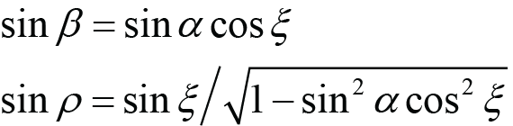 (Pitch angles from Lab angles), (A.4)
 (Lab angles from Roll angles), (A.5)
 (Lab angles from Pitch angles). (A.6)
In Eqs. (9) and (10) the Pitch and Lab polarization unit vectors are given in terms of the true s- and p-polarization unit vectors (which result from the Roll rotation). These may also be written in terms of the Cartesian unit vectors as follows:
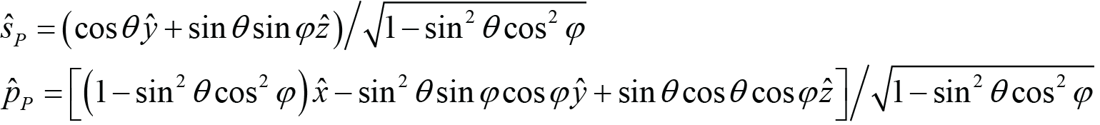 , (A.7)
 . (A.8)
References:
[1] D. A. Alessi, et al, “Low-dispersion low-loss dielectric gratings for efficient ultrafast laser pulse compression at high average powers,” Opt. and Laser Tech., Vol. 117, pp. 239-243, 2019.
[2] See PGL Technical Note “Gratings for High-average-power Ti:Sapphire Laser Systems.”
[3] See PGL Technical Note “The Grating Equation.”
[4] G. Kalinchenko, et al, “Positioning of Littrow mounted gratings in pulse compressors,” Proc. SPIE 9626, Optical Systems Design 2015: Optical Design and Engineering VI, 96261R (23 September 2015).
[5] K. Wei and L. Li, “Spectral beam combining gratings: high diffraction efficiency at a large deviation angle achieved around conical Littrow mounting,” Opt. Lett., Vol. 46, No. 18, pp. 4626-4629, 2021.
[6] O. Checkhlov, et al, “Development of Petawatt Laser Amplification Systems at the Central Laser Facility,” Proc. SPIE 6735, International Conference on Lasers, Applications, and Technologies 2007: High-Power Lasers and Applications, 67350J (2007).
[7] Proprietary PGL software based on the GD-Calc® engine by KJ Innovation (https://kjinnovation.com).
[8] T. Erdogan, “MLD vs. transmission gratings for the highest-efficiency, most-compact pulse compressors,” in OSA High-brightness Sources and Light-driven Interactions Congress 2020 (EUVXRAY, HILAS, MICS), OSA Technical Digest (Optica Publishing Group, 2020), paper HM2B.2.
5 Commerce Way, Carver, MA 02330, USA|+1.508.503.1719|sales@plymouthgrating.com