
Diffraction gratings can be understood using the optical principles of diffraction and interference. When light is incident on a surface with a profile that is irregular at length scales comparable to the wavelength of the light, it is reflected and refracted at a microscopic level in many different directions as described by the laws of diffraction. If the surface irregularity is periodic, such as a series of grooves etched into a surface, light diffracted from many periods in certain special directions constructively interferes, yielding replicas of the incident beam propagating in those directions.
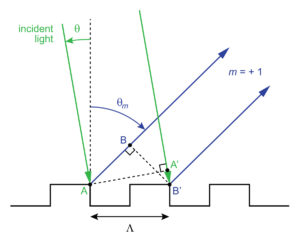
Referring to Figure 1, imagine a beam of light represented by the two green rays incident on the binary (rectangular profile) grating shown. The light is diffracted in many directions, only one of which is indicated by the blue rays. If the difference between adjacent green-blue ray paths diffracted off of identical locations on adjacent periods is equal to a multiple of the wavelength of light, the two blue rays interfere constructively.
Mathematically, the difference between paths AB and A’B’ is a multiple of the wavelength when AB – A’B’ = mλ, where m is an integer and λ is the wavelength of light (typically stated in nm). Since AB = Λsinθm and A’B’ = Λsinθ, where Λ is the grating period and θm and θ are the angles of diffraction and incidence, respectively, relative to the surface normal, the condition for constructive interference is
 The Grating Equation. (1)
This is the well-known Grating Equation. For a given angle of incidence, θ, it gives the angle of diffraction θm for each “order” m for which a solution to (1) exists. Often gratings are described by the frequency of grating lines instead of the period, where f (in lines/mm) is equal to 106/Λ (for Λ in nm). In terms of f the grating equation becomes
![]() (λ in nm; f in lines/mm). (2)
(λ in nm; f in lines/mm). (2)
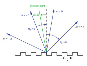
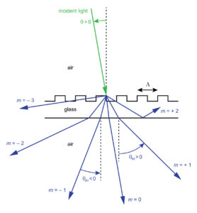
The larger the period Λ, or the lower the frequency f, the more orders there are. As an example, suppose a HeNe laser beam at 633 nm is incident on an 850 lines/mm grating. Referring to Figure 2, there will be three diffracted orders (m = –2, –1, and +1) along with the specular reflection (m = 0). This 0th order is typically not considered a diffracted order since it does not provide any angular dispersion (change in angle with change in wavelength).
Note the sign conventions for the angles. Incident light is shown traveling left-to-right, for which the angle θ ≥ 0. For diffracted light traveling left-to-right, θm ≥ 0, whereas for diffracted light traveling right-to-left, θm ≤ 0.
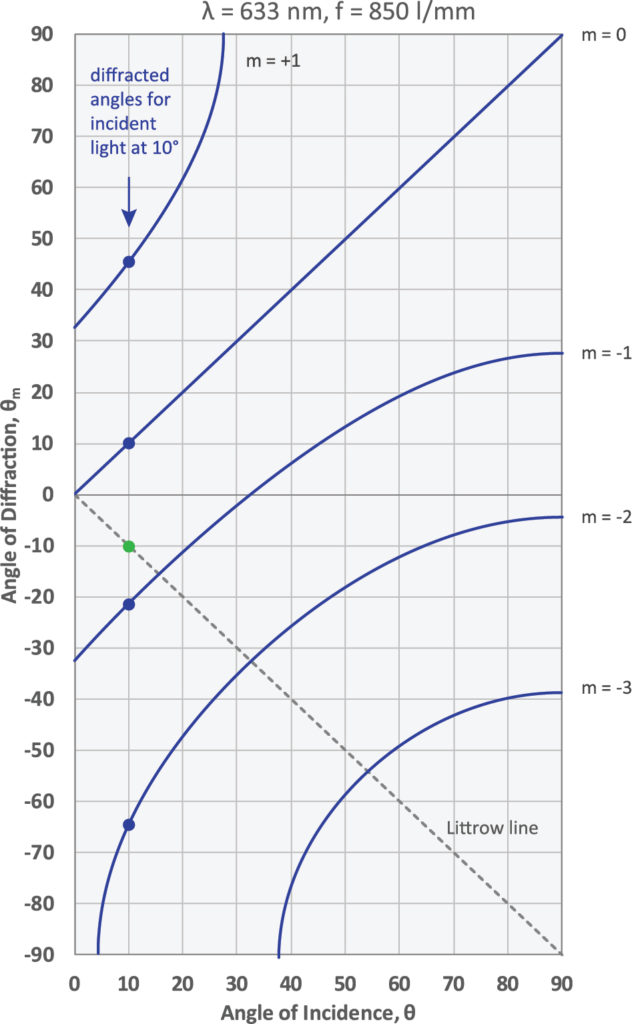
The dependence of the angles of diffraction on the angle of incidence can be more completely visualized on the graph shown in Figure 3. Here the specific case of θ = 10º illustrated in Figure 2 is indicated by the solid dots on the graph. From the graph it is apparent that different orders exist for different angles of incidence. For example, for θ smaller than about 5º only the +1st and –1st orders exist, while for θ larger than about 38º only the –1st, –2nd, and –3rd orders exist.
Try out PGL’s “Grating Calculator” tool to visualize the Grating Equation just as shown in Figure 3.
The graph in Figure 3 also shows a dashed line called the “Littrow line.” When the curve associated with a particular m < 0 order intersects this line, the angle of diffraction is equal and opposite to the angle of incidence. In other words, light is diffracted exactly along the path of the incident light. This type of retroreflection is called Littrow diffraction.
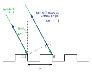
The condition for Littrow diffraction can be understood using the simple ray picture in Figure 4. Following the logic used in analyzing Figure 1, constructive interference along the Littrow direction occurs when the path difference between adjacent green-blue ray paths is given by (AB = 0) – 2A’B’ = mλ, or
 ,
,
where θL is called the Littrow angle. The same relation can also be derived by simply setting θm = – θ in the Grating Equation (1). Most often we are interested in the Littrow condition for the –1st order, for which the equation is
 The Littrow Condition. (3)
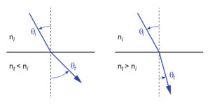
The discussion so far has assumed that the diffracted light is reflected off of the grating structure. A grating which predominantly reflects the diffracted light is called, not surprisingly, a reflection grating. A grating which predominantly transmits the diffracted light is called a transmission grating. When analyzing transmission gratings, care should be taken to properly account for refraction of light at the grating and any other interfaces. Refraction of a light ray at a planar interface between two media with different indexes of refraction is described by the well-known Snell’s Law
![]() ,
,
where ni and θi are the index of refraction and ray angle, respectively, in the incident medium, and nt and θt are the analogous quantities in the transmitted medium (see Figure 5). When nt is smaller than ni, light bends away from the normal to the interface (i.e., θt > θi), whereas when nt is larger than ni the opposite occurs.
To be more complete, if a grating is at an interface between two media with indexes ni and nt, the Grating Equation (1) is written as
 , (4)
, (4)
where nm is the index of refraction of the region into which the diffracted light travels. For the reflected orders, nm = ni, and the Grating Equation becomes
 .
.
For the transmitted orders, nm = nt, and the Grating Equation becomes
 .
.
A typical transmission grating is illustrated in Figure 6. Here the grating interface is shown as the front surface of a glass substrate. Since the incident and diffracted orders are all measured in air, the form of the Grating Equation in (1) should be used.
However, it is important to recognize that there may be orders that do not exist as solutions to (1), yet they exist and propagate inside the substrate. Examples are the +2nd and –3rd orders shown in Figure 6. These orders are totally internally reflected inside the substrate, and therefore do not propagate in the air region outside the substrate. Nevertheless they are real, and can emerge from the edge of the glass substrate.
For many gratings, especially those designed for use with lasers, it is desirable for all of the incident light to be diffracted into a single order to minimize loss in the overall system. The most straightforward way to realize a single order is to make the grating period Λ small enough to eliminate all other nonzero orders as solutions to the Grating Equation (1). How small Λ must be depends on the wavelength and the angle of incidence.
This constraint on the grating period is illustrated in Figure 7, which shows the cut-off ratio of wavelength to period, λ/Λ, for the lowest several diffracted orders as a function of the angle of incidence θ. For wavelength-period ratios above the m = –1 cut-off line, in the red-shaded region, no diffraction occurs at all; the period is simply too small. For ratios below the m = –1 cut-off line but above the m = +1 and m = –2 cut-off lines, in the yellow-shaded region, only a single –1st diffracted order exists. This is the region in which almost all PGL gratings fall.
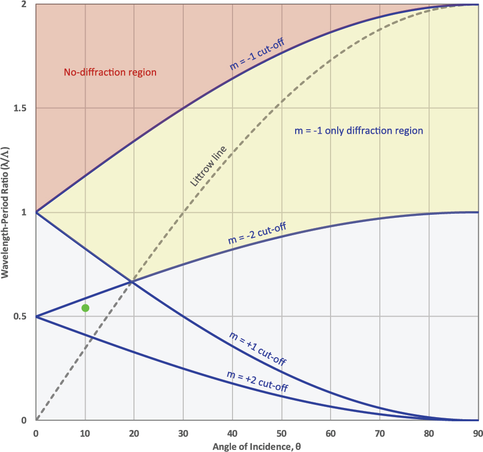
The cut-off lines for all other orders fall below those shown on the graph. The green dot illustrates the wavelength-period ratio and angle of incidence associated with the example of a 633 nm laser and 850 lines/mm grating highlighted in Figures 2 and 3. Since this point is below the m = –1, –2, and +1 cut-off lines, but above the m = +2 (and all other) cut-off lines, only these first three orders exist.
The Littrow line on the graph in Figure 7 connects the angle of incidence to the wavelength-period ratio. So for example, light with a wavelength exactly equal to the period of a grating (λ/Λ = 1) experiences Littrow diffraction at θ = 30º. For a given wavelength the largest possible period for which only a single diffracted order exists is exactly 1½ wavelengths (λ/Λ = 2/3). Single-order diffraction for such a period occurs at the Littrow angle of θL = arcsin(1/3) ≅ 20º.
5 Commerce Way, Carver, MA 02330, USA|+1.508.503.1719|sales@plymouthgrating.com