
Gratings are special because they introduce dispersion to the diffracted light waves. A wave experiences dispersion when one of its features, such as velocity or direction, depends on its frequency or, equivalently, its wavelength. Gratings are widely used to introduce a frequency-dependent time delay for short laser pulses. Chirped Pulse Amplification (CPA) is based on stretching and compressing after amplification short pulses using temporal dispersion from two or more gratings.
The principle of temporal dispersion resulting from light diffracted by a pair of gratings is illustrated in Figure 1.
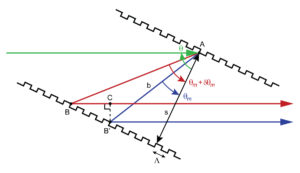
A light wave is incident at angle θ (represented by the green ray) on a first grating at point A. Two different wavelengths of light (the shorter one represented by the blue ray and the longer one by the red ray) are diffracted into order m at two different angles θm and θm + δθm, respectively. After diffracting off of an identical second grating arranged parallel to the first and separated by a distance s, the two rays emerge parallel to one another, forming an outgoing light wave with common phase fronts perpendicular to the rays. However, the red light travels a greater distance than the blue ray to arrive at the common phase front B’C, thus effectively delaying this light by a time δτ equal to the difference in path length divided by the speed of light c, or
 .
.
From the figure it can be seen that

where the minus sign in front of the expression for BC is needed since θm and θm + δθm are both < 0. Combining these relations, we find the difference in delay time for the two light waves
 .
.
We can find the rate of change of δτ with change in angle θm by taking the limit of the above expression as δθm goes to zero and using the definition of a derivative and the Grating Equation sinθm = sinθ + mλf [1], which gives
 .
.
To find the rate of change of the time delay τ with change in wavelength λ we may use the chain rule of differentiation
 ,
,
and the angular dispersion dθm/dλ = mf/cosθm from [2]. The result is
 , (1)
, (1)
which has units of ps/nm when λ is in nm, f is in lines/mm, s is in meters, and c is in meters/sec. dτ/dλ is a measure of the temporal dispersion resulting from the pair of gratings. Often it is more convenient to write the temporal dispersion per meter of grating separation. This quantity is called the temporal dispersion parameter, and it is generally denoted by D. Rearranging (1) we see
 , (2)
, (2)
where the subscript “⊥” denotes that the grating separation is measured along the direction normal to the grating surfaces. This important parameter can be interpreted as follows: for each meter of separation s between two parallel gratings, the difference in propagation delay time dτ between two wavelengths of light separated by dλ can be approximated by the expression on the right side of (2) multiplied by dλ. Note that this time difference is proportional to the grating frequency f squared. Hence higher frequency gratings yield much higher temporal dispersion.
Sometimes it is more convenient to measure the separation between the two gratings along the primary ray path of light, or the distance denoted b in Figure 1. Since b = s/cosθm, (2) then becomes
 . (3)
. (3)
Note that the temporal dispersion parameter D according to (2) and (3) is positive, regardless of whether the order m or the angle of diffraction are positive or negative. Therefore the delay time increases as the wavelength increases. In other words, red frequency components (longer wavelengths) are always delayed more than, or lag, blue frequency components (shorter wavelengths) in a parallel grating pair arrangement like the one shown in Figure 1.
As a numerical example, suppose light from a laser centered at 800 nm is incident on a parallel pair of 1480 lines/mm gratings at an angle of 54º. The angle of diffraction for the –1st order is –22º. The resulting temporal dispersion according to (2) is D⊥ = 7.3 ps/nm per meter of separation. Therefore if the two gratings are 1 meter apart, the extreme frequency components of an ultrafast pulse that span a range of about 100 nm become separated in time by about 730 ps. If the incident pulse is about 20 fs wide, the pulse width is increased by a factor of over 36,000.
If the same pulse is incident on the same pair of gratings at an angle of 22º, such that the diffracted angle for the –1st order is –54º, the dispersion according to (2) is D⊥ = 28.8 ps/nm per meter of separation, or about four times larger. The incident pulse for this arrangement is stretched by a factor 144,000 to a width of about 2.9 ns.
As with the Grating Equation and angular dispersion, it is helpful to visualize temporal dispersion by plotting it as a function of the angle of incidence for a certain wavelength. Figure 2 shows how the temporal dispersion of the –1st order depends on angle of incidence at 800 nm for three different grating frequency values.
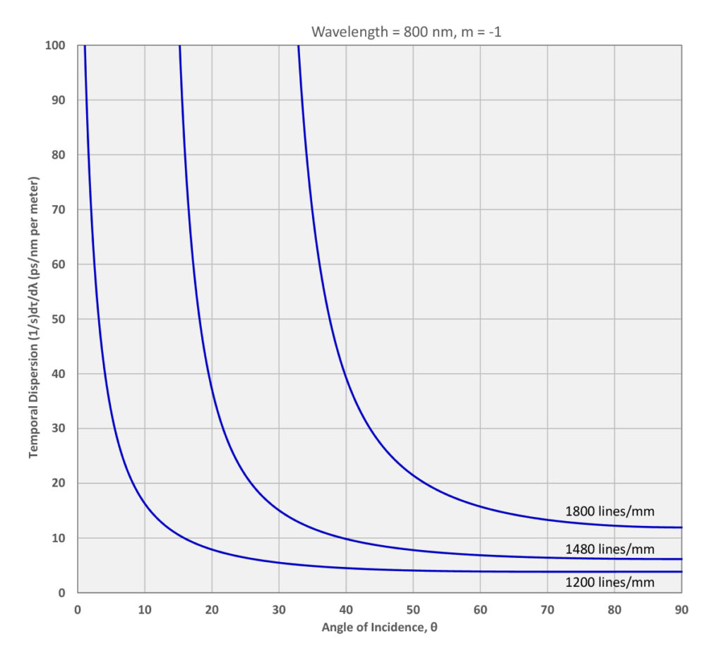
Try out PGL’s “Grating Calculator” tool to visualize Temporal Dispersion just as shown in Figure 2.
As with angular dispersion, the temporal dispersion is larger for higher grating frequencies at a given angle of incidence. Furthermore it increases very rapidly at smaller angles of incidence, as the angle of diffraction approaches –90º.
On a final note, the astute observer might be disturbed by the lateral separation between the parallel light rays emerging from the grating pair in Figure 1. The beam of light now has a “spectral shear” across its wavefront. For many applications such a shear is not desirable, but fortunately it can be eliminated by passing the sheared beam through a second pair of parallel gratings identical to the first, but with opposite orientation. The resulting dispersion is double that imparted by the first pair of gratings. Alternative solutions to the lateral shear problem and other systems issues are discussed in another Technical Note.
5 Commerce Way, Carver, MA 02330, USA|+1.508.503.1719|sales@plymouthgrating.com