
Gratings are special because they introduce dispersion to the diffracted light waves. A wave experiences dispersion when one of its features, such as velocity or direction, depends on its frequency or, equivalently, its wavelength. Perhaps the most widely used dispersive property of gratings is angular dispersion—the fundamental enabler for most spectroscopy measurements and instruments.
One need look no further than the Grating Equation [1] to understand angular dispersion:
![]() (λ in nm; f in lines/mm). (1)
(λ in nm; f in lines/mm). (1)
For a given grating frequency f and angle of incidence θ, the Grating Equation shows how the diffracted angle θm for order m depends on the wavelength of light λ. Differentiating both sides of (1) with respect to λ, we find
 , (2)
, (2)
or, in terms of the known quantities and wavelength,
 . (3)
. (3)
In (2) and (3) f is assumed to be in units of lines/nm for simplicity. The angular dispersion dθm/dλ has units of radians/nm, and may be multiplied by 180/π to obtain units of degrees/nm.
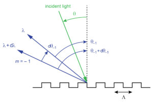
Figure 1 illustrates angular dispersion from a ray point of view. Here light at two similar but distinct wavelengths λ and λ + dλ is diffracted into the –1st order at the two angles θ–1 and θ–1 + dθ–1, respectively.
The simple differential relations in (2) and (3) can be used to quickly and reasonably accurately estimate the angular variation dθ–1 that results from a small wavelength change dλ. For example, suppose light from a laser centered at 800 nm is incident on a 1480 lines/mm grating at an angle of 54º. The angle of diffraction for the –1st order at 800 nm is –22.02º, and at 810 nm it is –22.94º, so the angle change for dλ = 10 nm is exactly dθ–1 = –0.92º. Approximating the angle change using (2), we calculate dθ–1/dλ = –0.092 deg/nm, which also suggests a –0.92º angular change for a 10 nm wavelength change! Doing the same calculation for dλ = 50 nm, we get an exact angular change of –4.66º and an approximate change from (2) of –4.60º, again demonstrating that the approximation is excellent, though not perfect, for some very practical numbers.
As with the Grating Equation, it is helpful to visualize angular dispersion by plotting it as a function of the angle of incidence for a certain wavelength. Figure 2 shows how the angular dispersion of the –1st order depends on angle of incidence at 800 nm for three different grating frequency values.
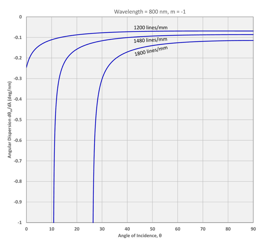
Try out PGL’s “Grating Calculator” tool to visualize Angular Dispersion just as shown in Figure 2.
Note that the absolute value of the angular dispersion is larger for higher grating frequencies. Furthermore it increases very rapidly at smaller angles of incidence, as the angle of diffraction approaches –90º.
5 Commerce Way, Carver, MA 02330, USA|+1.508.503.1719|sales@plymouthgrating.com