
Diffraction gratings can be understood using the optical principles of diffraction and interference. When light is incident on a surface with a profile that is irregular at length scales comparable to the wavelength of the light, it is reflected and refracted at a microscopic level in many different directions as described by the laws of diffraction. If the surface irregularity is periodic, such as a series of grooves etched into a surface, light diffracted from many periods in certain special directions constructively interferes, yielding replicas of the incident beam propagating in those directions.
The PGL Technical Note “The Grating Equation” [1] describes how to predict the different directions light propagates from a grating using optical interference. How much light diffracts into each direction is determined by the principle of diffraction at a microscopic level. In other words, the profile of the grating grooves dictates the efficiency with which light diffracts into each of the orders. Formally, the diffraction efficiency (DE) associated with an order m is the ratio of the optical power Pm that propagates away from the grating in order m to the optical power Pinc incident on the grating, or
 . (1)
. (1)
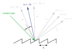
For larger-period or lower-frequency gratings in which many orders exist, the choice of groove profile to direct light into a particular order is intuitive. Referring to the example of a reflection grating in Figure 1, to direct as much light as possible into a specific order –M, the grating should be blazed as shown in the figure with the blaze angle chosen so that the incident and –Mth order rays obey the law of reflection (equal angles relative to the normal to the surface of reflection).
For many gratings, especially those designed for use with lasers, it is desirable for all of the incident light to be diffracted into a single order to minimize loss in the overall system. When interference permits multiple diffracted orders, even a perfectly optimized groove profile is not sufficient to achieve nearly 100% DE into a single order. The most effective way to channel as much light as possible into a single order is to make the grating period Λ small enough to eliminate all other nonzero orders as solutions to the grating equation (see Figure 7 in [1]).
It might seem reasonable that the highest possible diffraction efficiency in one order should occur when the grating equation permits only a single nonzero order and the groove profile is blazed according to the law of reflection as shown in Figure 1. However, this intuition is not accurate when the wavelength of light is comparable to or larger than the grating period.
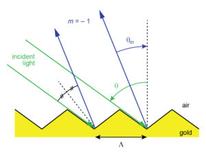
To verify this claim, consider the following example. Suppose light from a Ti:Sapphire laser at 800 nm is incident at 54º on a 1480 lines/mm gold reflection grating, as illustrated by the green rays in Figure 2. According to the grating equation, the only solutions are m = 0 and m = –1, and the –1st order is diffracted at –22º (blue rays). The apparently optimal blaze profile would incorporate the reflective surface inclined at an angle of 38º relative to horizontal. This surface forms the left side of each grating tooth shown in the figure.
Because light rays do not directly strike the surface on the right side of each triangular grating tooth shown in the particular profile of Figure 2 (which we’ll refer to as “Blaze 1”), it also seems reasonable that the shape of the right surface should not affect the DE. Two alternative groove profiles are illustrated in Figure 3 (labeled “Blaze 2” and “Blaze 3”). Also shown in this figure is a binary profile.
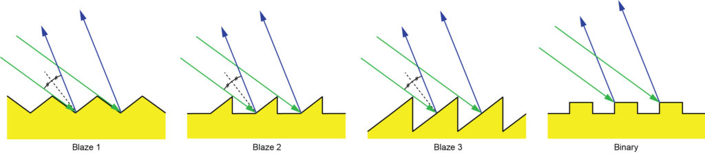
Figure 4 shows the results of a Rigorous Coupled Wave Analysis (RCWA) calculation of the –1st order DE for each of the four groove profiles shown in Figure 3. The depth and duty cycle of the binary grating have been optimized to achieve the highest efficiency for the parameters used in this example, with values of 165 nm and 52%, respectively.
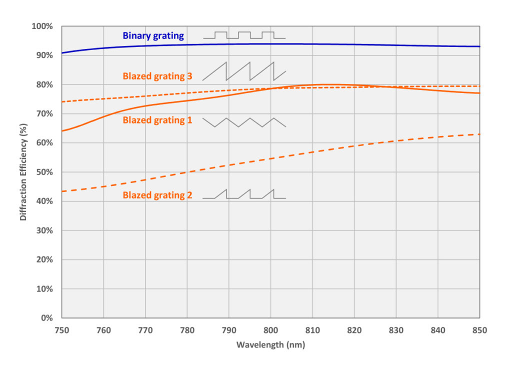
The results might be surprising – all of the blaze profiles result in poorer diffraction efficiency than the binary profile! Furthermore, despite the intuition that the light should never “see” the part of the profile on the right side of each tooth, the shape of this part of the tooth does in fact have a significant impact on the efficiency. The explanation for these results lies in the relative size of the wavelength of light to the features of the profile. Because the wavelength (800 nm) is larger than the period (676 nm) and any of the other features, macroscopic intuition based on rays, reflection, and refraction is not applicable. Instead the light can be thought of as averaging over the relative amounts of gold and air. When the incline of the reflective surface is fixed by the law of reflection, the relative amount of the two materials is unnecessarily constrained. By using a binary profile and adjusting the depth and duty cycle, we are able to fine-tune the relative amount and the averaging effect, and thus achieve the best overall efficiency.
This example demonstrates why it is generally not necessary to utilize complex, asymmetric groove profiles (such as traditional blazing) in very high DE gratings for laser applications. For most of these gratings, it is sufficient to adjust the depth, duty cycle, and sidewall taper angle of a symmetric groove profile. On rare occasions more complex profiles are required, though these require more challenging manufacturing steps and hence tend to impact yield and cost.
The principle that the most effective way to achieve high diffraction efficiency in one order is to ensure the grating period is small enough to eliminate all higher orders can be further generalized. To achieve the highest possible diffraction efficiency in a single order, minimize all other places the light could possibly go.
Besides higher orders in the desired direction, other possible “leaks” for the light include, for example, absorption, scattering, and reflected orders in a transmission grating (or vice versa). This principle helps to understand why some laser grating types exhibit higher DE than others. Table 1 summarizes typical values for the DE achieved in practice for three main types of laser gratings: multilayer dielectric (MLD) reflection gratings, transmission gratings, and gold reflection gratings. For completeness, the table also summarizes the spectral and angular ranges over which high DE can be achieved for each grating type.
Table 1: Comparison of diffraction efficiency for three main grating types:
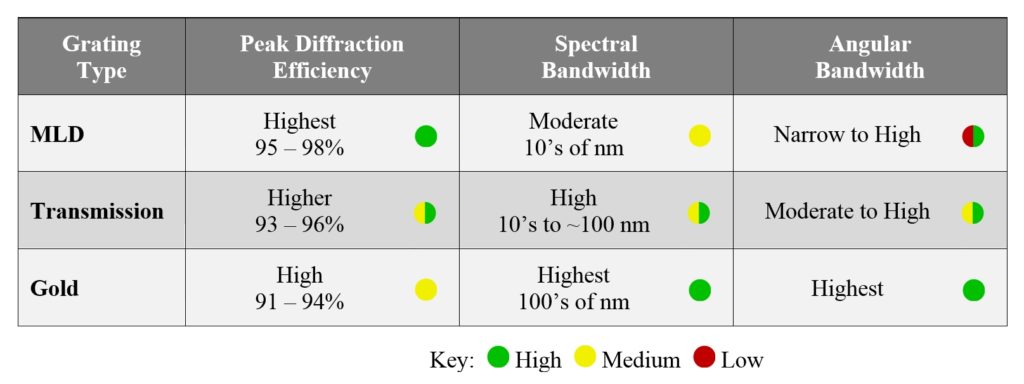
While gold gratings that support only m = –1 and 0 orders typically achieve DE > 90%, they have the lowest efficiency of the three types primarily due to absorption of light in the gold. While metals can make excellent mirrors, there is always some absorption. Scattering can also play a role when the gold surface exhibits significant roughness. Gold gratings are very popular, however, because of the superior spectral and angular bandwidth properties. They are especially important for compression of ultrashort pulses (10’s of fs) in lasers based on Ti:Sapphire and optical parametric amplification.
Transmission gratings can be made virtually absorption-free, but in addition to the m = 0 order in transmission there are m = –1 and 0 reflected orders attempting to rob light from the desired –1st transmitted order. Preventing light from leaking into the reflected orders requires very tight tolerances on the groove profile. So while transmission gratings can in theory achieve very high DE, they are the least forgiving in terms of manufacturing. Incorporation of antireflection (AR) layers into the grating design can improve the peak DE, but these modifications also tend to make the already tight tolerances even tighter.
MLD gratings achieve the highest peak DE values both in theory and in practice. Like transmission gratings, absorption is minimal, and like gold gratings, the leakage into the transmitted orders can be effectively eliminated with a sufficiently high reflectivity thin-film stack. So to achieve high DE the design need only balance light between two possible output channels: the m = –1 and m = 0 orders. The downside of MLD gratings is that this balancing act is based on an additional optical interference degree of freedom. As a result it is difficult to obtain high DE over a wide range wavelengths and angles, especially simultaneously. In fact, high DE is generally limited to angles very close to Littrow, except when the ratio of wavelength to period is approximately 1.8 (Littrow angle ~ 65º). For this special case the angular range can be very broad, though generally at the expense of spectral bandwidth.
In summary, MLD gratings exhibit the highest DE, but are the most limited in the choice of dispersion and ranges of wavelength and incidence angle. Gold gratings offer the easiest solution to achieve relatively high DE over very broad wavelength and angle ranges for a wide variety of dispersion values, but they always exhibit some absorption. Transmission gratings achieve higher DE than gold and they are also fairly flexible in terms of dispersion, but the higher DE comes at a cost due to manufacturing tolerances and the wavelength and angular ranges are not as broad as those of gold gratings.
Below are some examples of how diffraction efficiency depends on various grating structural parameters as well as wavelength and angle of incidence. An MLD grating is chosen for these examples to highlight the sensitivity to wavelength and angle discussed above.
Figure 5 shows a theoretical model of the dependence of diffraction efficiency on grating groove depth at several different duty cycles for 1030 nm light incident on a 1760 lines/mm MLD grating at a 60º angle of incidence. The Littrow angle for this wavelength-frequency combination is 65.0º. The MLD thin-film stack is optimized for this wavelength and angle range.
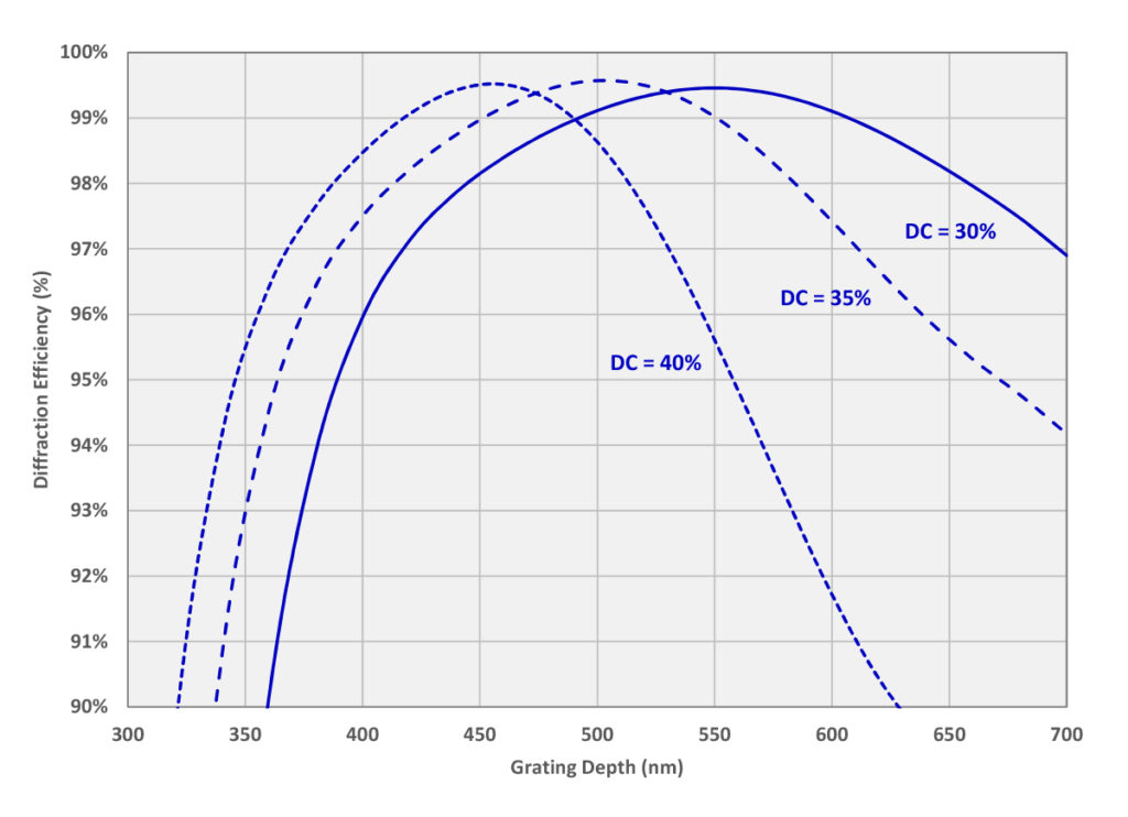
Note that lower duty cycles require deeper grooves, which supports the observation made above that the light can be thought of as averaging over the relative amounts of high- and low-index material.
Figure 6 illustrates the dependence of DE on wavelength for several different angles of incidence for the same grating. For these calculations the grooves are assumed to be 500 nm deep with a duty cycle of 35%.
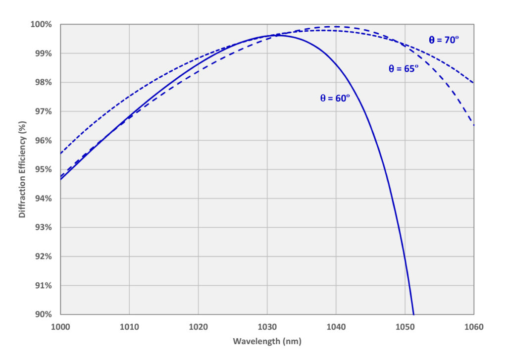
Because the grating was optimized for λ = 1030 nm and θ = 60º, the 60º angle curve peaks right at 1030 nm. For this design even higher DE is achieved at the Littrow angle of 65.0º, though at a slightly longer wavelength. Also note that the spectral bandwidth is somewhat broader at angles on the high side of Littrow (here 70º). This result is common, and one reason why MLD-based pulse compressors are often designed with light incident at the larger angle and diffracted at the smaller angle.
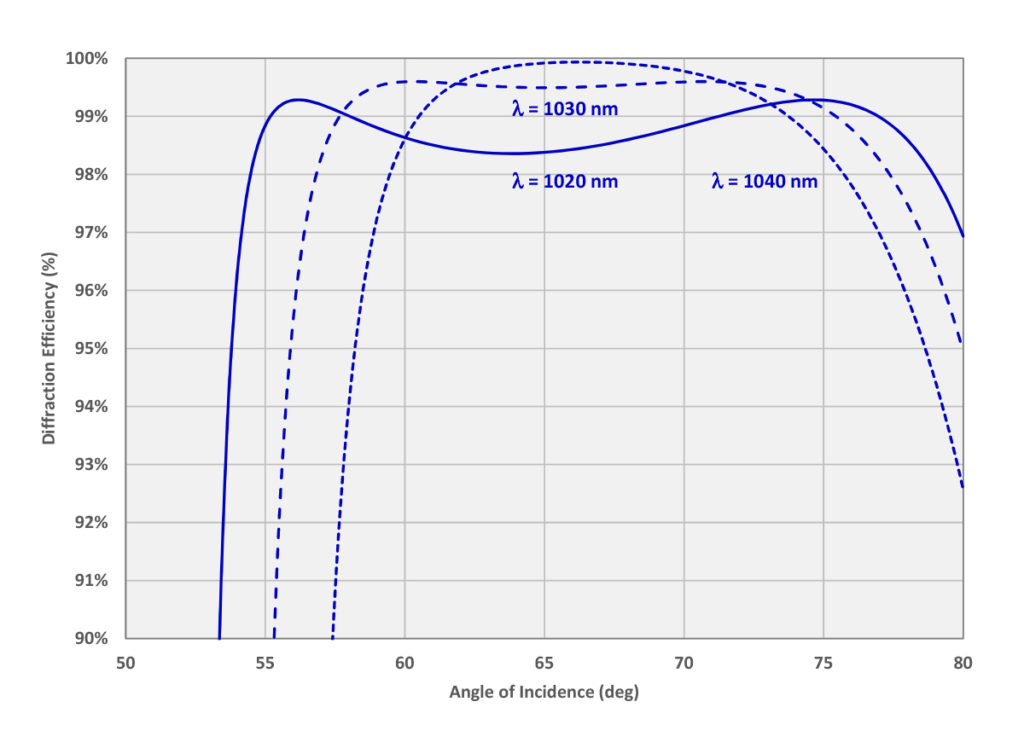
Figure 7 shows the dependence of DE on angle of incidence for several different wavelengths for the same grating as in Figure 6. The Littrow angles for 1020, 1030, and 1040 nm are 63.8º, 65.0º, and 66.2º, respectively. It is apparent that the curves are at least qualitatively symmetric about the Littrow angle for each wavelength.
There are many considerations that should be taken into account when designing and manufacturing a grating with very high diffraction efficiency. Foremost among these is elimination of all undesired places light could possibly go, which generally starts with the restriction of the wavelength-period ratio to the range where only the m = –1 diffracted order is possible.
5 Commerce Way, Carver, MA 02330, USA|+1.508.503.1719|sales@plymouthgrating.com