
Contrary to popular belief MLD gratings can be designed with a wide range of periods to provide the highest overall efficiency pulse compressors that are as compact and flexible as those based on transmission gratings.
All-dielectric diffraction gratings are well suited for chirped-pulse-amplification (CPA) lasers with pulse lengths as short as 100’s of fs and moderate bandwidths up to 10’s of nm. Dielectric gratings provide higher diffraction efficiency and laser-induced damage threshold than gold or other metallic reflection gratings, resulting in higher overall compressor efficiency and more compact compressor formats, and they exhibit extremely low absorption loss. Low loss is especially important for high-repetition-rate, high-average-power (HAP) lasers. The two primary types of all-dielectric gratings are surface-relief transmission [1] and multi-layer dielectric (MLD) reflection gratings [2]. Here we compare these two types of gratings for 1 μm laser applications (e.g., 1030 nm Yb-based systems) in terms of compressor efficiency and compactness, including practical considerations like manufacturability.
Transmission gratings may be conveniently operated at the Littrow angle of incidence, resulting in simple compressor geometries and alignment schemes. They exhibit relatively consistent diffraction efficiency as well as spectral and angular bandwidth performance over a broad range of grating periods for a given wavelength. Drawbacks of transmission gratings include difficulty designing and achieving very high diffraction efficiency and material dispersion associated with propagation through the substrate.
MLD gratings achieve the highest efficiencies of all grating types, do not introduce material dispersion, and have comparable spectral bandwidth performance to that of transmission gratings. The main shortcoming of MLD’s is a generally narrow angular bandwidth with high efficiency occurring only at the Littrow angle, except for the special case of a period-to-wavelength ratio of about 0.55, associated with a Littrow angle of about 66°. This trait is often considered to be a significant design limitation, since MLD’s are reflection gratings, and thus require an appreciable deviation angle between the incident and diffracted beams.
In this technical note we show that in contrast to conventional wisdom transmission gratings can achieve very high efficiencies, and MLD gratings can be used with a very wide range of grating periods, allowing both types of gratings to yield extremely high-efficiency and compact compressor designs using even a single grating. However, because high-efficiency MLD’s are significantly more manufacturable than transmission gratings, MLD’s are a better practical choice for most applications.
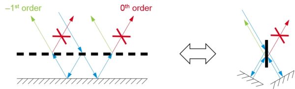
MLD gratings are interferometric devices. The principle of operation is analogous to a Michelson interferometer, where the grating layer in the MLD performs the role of the 50% beamsplitter in the Michelson, and the high-reflecting thin-film stack acts like the two mirrors (see Fig. 1). Just the right accumulation and balance of phase upon diffraction, propagation, and thin-film reflection is required to channel all of the light into the –1st reflected order. In an MLD grating there are only two places the light can go: into the –1st diffracted order or into the 0th order (specular reflection). The distribution of light between these two is primarily controlled by interference associated with the thin film layers under the grating, which can be manufactured with high accuracy. Since the job of the grating layer is simply to split the light into two channels, the tolerances on the grating tooth parameters – depth, duty cycle, and shape – are not overly tight.
In a transmission grating there are four places the light can go: the −1st and 0th orders in both transmission and reflection. The distribution among these is entirely controlled by the grating tooth parameters, resulting in tight tolerances on these. Unless the grating tooth region is specially designed to act as an anti-reflection (AR) coating to eliminate the two reflected orders, the maximum –1st order transmission efficiency for a simple binary-tooth design is limited to the low 90’s % range for high-dispersion gratings [1]. AR performance can be built in by one of several approaches: forming large tapers in the grating teeth [1], incorporating explicit thin-film AR layers above or below the grating [3], or using a combination of high- and low-index materials in the teeth themselves [4]. Unfortunately, large, controlled tapers are difficult to realize in practical etching processes, and, as shown below, incorporation of additional materials significantly tightens the tolerances on the depth and duty cycle.
Generally MLD reflection gratings are used in only the in-plane (IP) configuration, where both the incident and diffracted beams lie in the grating plane (defined to be the plane perpendicular to the grating lines and the substrate surface). This configuration requires a broad angular bandwidth, and thus in-plane MLD gratings should have a period-to-wavelength ratio of about 0.55. For 1030 nm laser systems, only gratings with groove densities of about 1760 lines/mm are possible. However, MLD gratings may also be operated in the out-of-plane (OOP) configuration, with only a small impact on diffraction efficiency [5]. Using the OOP geometry, a much wider range of groove densities are possible for MLD gratings, greatly increasing flexibility and possibilities for optimizing compressor designs.
Consider a 1030 nm Yb-based laser system designed for a 500 fs gaussian pulse with an associated bandwidth of about 3 nm. Assume the beam is 1 cm in diameter, the pulse is stretched to 100 ps, and it should be compressed in a compact, single-grating compressor with the highest possible efficiency. Typically such systems use 1700 – 1760 lines/mm gratings, and thus we first compare transmission grating solutions to both in-plane and out-of-plane MLD solutions.
Optimized grating designs were created for four different grating types at 1760 lines/mm: a simple binary transmission grating (Tx-SL), a transmission grating incorporating a high-index layer in the grating teeth (Tx-ML), an in-plane MLD grating (MLD-IP), and an out-of-plane MLD grating (MLD-OOP). The transmission gratings were designed to operate at the Littrow angle of 65.0°, and the MLD gratings were designed to operate with an 8° full deviation angle between the incident and –1st order diffracted beams. Plots of the theoretical diffraction efficiency vs. angle of incidence and wavelength are shown in Fig. 2.
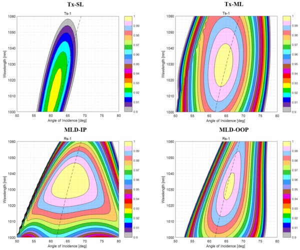
Fig. 3 shows the diffraction efficiency vs. wavelength for each grating design at the intended angle of incidence (the 65.0° Littrow angle for the transmission gratings, 61.3° for the in-plane MLD grating, and 65.4° with a 4.4° grating roll angle for the out-of-plane MLD grating). The simple binary transmission grating achieves just under 92% efficiency. A more optimal transmission grating design incorporating a high-index layer in the grating teeth (following [4]) achieves over 99.5%. Both in-plane and out-of-plane MLD designs also achieve over 99.5%. Although the in-plane MLD design has the narrowest spectral bandwidth, all four grating types readily achieve a sufficiently broad bandwidth for pulses ~ 0.5 ps or longer.
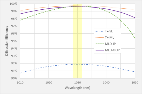
Fig. 4 shows the overall compressor efficiency based on a simple calculation of the average over a 3 nm bandwidth of the values of the single-grating curves from Fig. 3 raised to the 4th power, since the beam encounters the grating four times in the compressor. The overall compressor efficiency for a 20 nm bandwidth is also shown for comparison. The multilayer Tx grating and both in-plane and out-of-plane MLD grating designs exhibit comparable efficiencies well above 95%.
Many grating designs are theoretically possible, including those with diffraction efficiencies of 100%, but not necessarily practically realizable. It is important to consider the manufacturability of grating designs. A straightforward and effective measure of the manufacturability is the “Manufacturing Tolerance” (MT), defined to be the range of depth values (normalized to the design depth) times the range of duty cycle values over which a design achieves a particular diffraction efficiency. The higher the tolerance, the more manufacturable the design. For example, a grating which can achieve a 95% efficiency for depth values of 500 nm ± 50 nm and duty cycle values in the range 30 – 40% would have a 95% Manufacturing Tolerance of (100/500)×0.1 = 0.02.
The graph in Fig. 4 also shows the 97% and 99% Manufacturing Tolerance for each of the four designs. The target value of 0.02 is a useful reference. Designs with MT below this value are very challenging to manufacture, while those above are fairly straightforward. A design that does not achieve the desired tolerance value (e.g., 97% or 99%) by definition has an MT = 0.
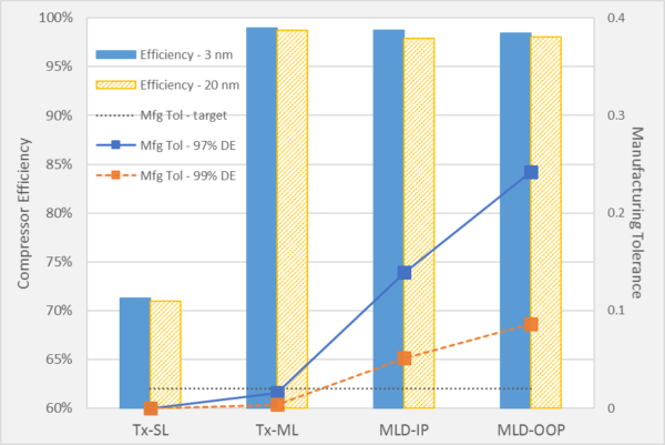
Clearly the MLD grating designs are much more manufacturable than the transmission grating designs. Interestingly, the out-of-plane MLD design is also significantly more manufacturable than the in-plane design. Manufacturability applies not only to whether or not a grating can be made to work at all, but also to the uniformity of the diffraction efficiency and the ability to scale the grating to larger sizes. A spatially nonuniform efficiency can distort the beam and its focusing properties, and also lead to temporal pulse distortion through spatio-temporal coupling in the compressor.
For this example we assume the same laser and pulse requirements described in Example 1 above, but we consider a groove density that is not compatible with an in-plane MLD geometry having an appreciable deviation angle, so that we can directly compare transmission designs with an out-of-plane MLD design. Furthermore, we choose a lower groove density (larger grating period), since simple binary transmission gratings perform increasingly better for larger periods.
Optimized grating designs were created for three different grating types at 1600 lines/mm: a simple binary transmission grating (Tx-SL), a transmission grating incorporating a high-index layer in the grating teeth (Tx-ML), and an out-of-plane MLD grating (MLD-OOP). The transmission gratings were designed to operate at the Littrow angle for 1030 nm of 55.5°, and the MLD grating was designed to operate with an 8° full deviation angle between the incident and –1st order diffracted beams. Plots of the theoretical diffraction efficiency vs. angle of incidence and wavelength are shown in Fig. 5.
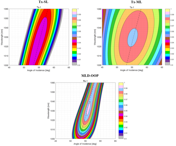
Fig. 6 shows the diffraction efficiency vs. wavelength for each grating design at the intended angle of incidence (the 55.5° Littrow angle for the transmission gratings, and 55.8° with a 4.8° grating roll angle for the out-of-plane MLD grating). The simple binary transmission grating achieves just over 94% efficiency. A more optimal transmission grating design incorporating a high-index layer in the grating teeth (following [4]) achieves about 98.5%. The out-of-plane MLD design achieves over 99%. In this case both transmission designs show broader bandwidth performance than the MLD design, though all three grating types have a sufficiently broad bandwidth for pulses ~ 0.5 ps or longer.
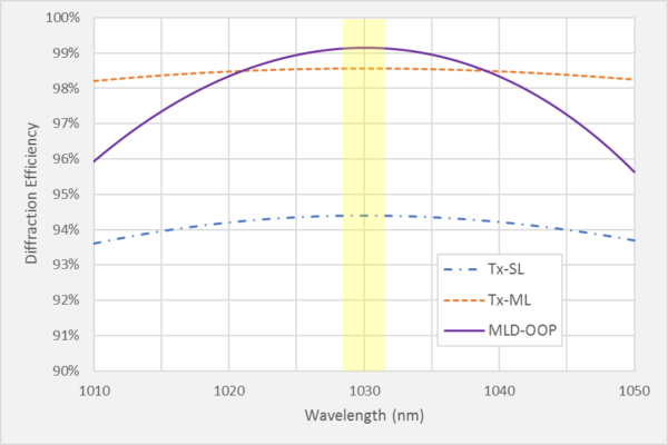
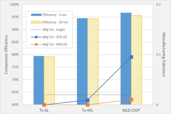
Fig. 7 shows the overall compressor efficiency based on a simple calculation of the average over a 3 nm bandwidth of the values of the single-grating curves from Fig. 6 raised to the 4th power, since the beam encounters the grating four times in the compressor. The overall compressor efficiency for a 20 nm bandwidth is also shown for comparison. The multilayer Tx grating and the MLD grating designs exhibit comparable efficiencies. Fig. 7 also shows the 97% and 99% Manufacturing Tolerance for each design. None of the designs are suitable for 99% performance, and the MLD grating design is clearly much more manufacturable than either of the transmission grating designs for high-efficiency operation.
Next we address compactness by looking at possible compressor configurations for this example. Compressors can be made with four, two, or one grating. With fewer than four gratings, the simplest way to double-pass a grating is to translate the beam between passes using roof-mirror assemblies. For this reason, the grating size increases roughly in proportion to the number of passes; the grating in a single-grating compressor is roughly four times larger than the size required for a four-grating compressor.
Fig. 8 shows ray diagrams of example compressors based on a single 1600 lines/mm grating. Each provides 33.3 ps/nm of dispersion in order to compress the 100 ps pulse over 3 nm. The first (top) is for either of the transmission gratings in this example, and the second (bottom) is for the out-of-plane MLD grating with an 8° deviation angle. In both cases the gratings are 70 mm long and 30 mm wide. Ignoring size constraints associated with mounts, the minimum compressor volume is 730 cm3 for the transmission grating compressor and 1,030 cm3 for the MLD grating compressor. The volumes are comparable, with the MLD requiring a slightly larger volume due to the smaller angle. Both compressors use a pair of roof-mirror assemblies – one for horizontal beam translation and one for vertical beam translation. Note the vertical assembly for the OOP MLD compressor uses three mirrors (an odd number of bounces) in order to eliminate lateral spatial dispersion.
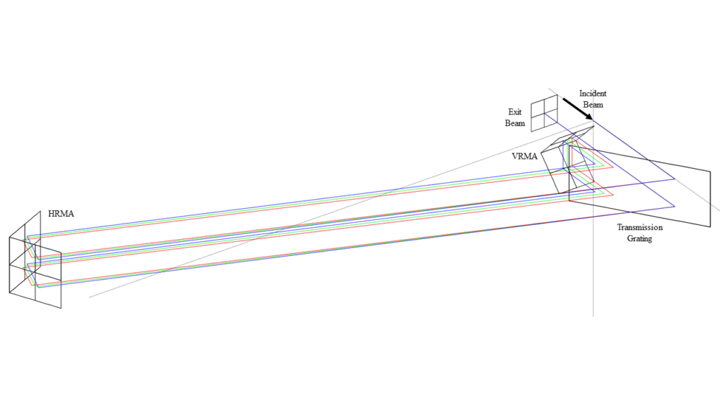
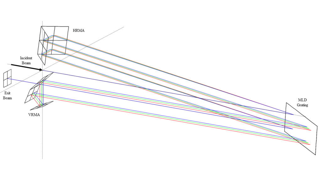 Figure 8: Examples of 33.3 ps/nm compressor designs based on a single transmission grating (top) and a single out-of-plane MLD grating (bottom). Blue, green, and red rays correspond to 1028.5, 1030, and 1031.5 nm, respectively. HRMA = horizontal roof mirror assembly, and VRMA = vertical roof mirror assembly.
[1] F. Koch, D. Lehr, O. Schönbrodt, T. Glaser, R. Fechner, and F. Frost, “Manufacturing of highly dispersive, high-efficiency transmission gratings by laser interference lithography and dry etching,” Microelectron. Eng. 191, 60-65 (2018).
[2] J.A. Britten, W.A. Molander, A.K. Komashko, and C.P. Barty, “Multilayer dielectric gratings for petawatt-class laser systems,” Proc. SPIE 5273 (2004).
[3] K. Nagashima, A. Kosuge, Y. Ochi, and M. Tanaka, “Improvement of diffraction efficiency of dielectric transmission gratings using anti-reflection coatings,” Opt. Express. 21, 18640-18645 (2013).
[4] H. Rathgen and H. L. Offerhaus, “Large bandwidth, highly efficient optical gratings through high index materials,” Opt. Express. 17, 4268-4283 (2009).
[5] D.A. Alessi, H.T. Nguyen, J.A. Britten, P.A. Rosso, and C. Haefner, “Low-dispersion low-loss dielectric gratings for efficient ultrafast laser pulse compression at high average powers,” Opt. and Laser Tech. 117, 239-243 (2019).
5 Commerce Way, Carver, MA 02330, USA|+1.508.503.1719|sales@plymouthgrating.com