
Diffraction gratings are critical components in most chirped-pulse-amplification (CPA) laser systems. There are many different grating types (metal, all-dielectric, and hybrid metal-dielectric reflection gratings, as well as transmission gratings), and even more trade-offs relating to diffraction efficiency, spectral and angular bandwidth, polarization, laser-induced damage threshold (LIDT), and temporal dispersion, to name a few. Choosing the right grating for a given laser system can be confusing. In this technical note we describe how one can make the best grating selection for a given set of laser requirements.
Wavelength:
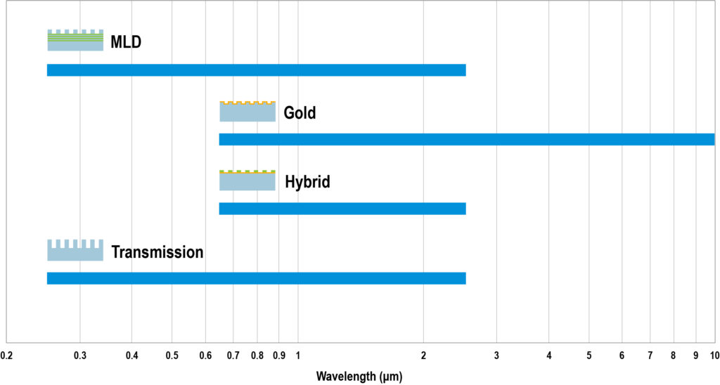
When selecting the right grating a good starting point is wavelength. After all, the absolute value, range, and stability of a laser’s wavelength are some of the most fundamental defining features of the laser. The wavelengths over which different grating types may operate are constrained by the wavelength dependence of material properties such as absorption, reflection, and transmission. Based on these constraints, Fig. 1 gives the approximate wavelength ranges over which each of the four major grating types are possible.
For the chart above and in fact all of the charts in this technical note, several assumptions are made. We assume manufacturable values for the grating tooth shape, including the depth, duty cycle, and sidewall taper angle. We consider only reasonable manufacturing tolerances for these and other parameters, such as thin-film coating thicknesses and refractive index values. And we include only well-established materials with proven laser-induced damage threshold (LIDT) performance. Grating designs that do not follow these assumptions are possible, and may be considered for special cases. Such designs will be likely difficult to fabricate and therefore risky, costly, or both.
The all-dielectric MLD and transmission gratings are assumed to be made from established oxide-based glass substrates and thin-film coating materials, which achieve low loss from ultraviolet (UV) to near-infrared (IR) wavelengths. The best-performing and most practical metallic reflection gratings are based on gold, which has good reflectivity from long visible to far-IR wavelengths. Hybrid metal-dielectric gratings thus operate over a wavelength range that is the intersection of the dielectric and gold ranges.
Damage:
The next logical requirement to consider when selecting gratings is the final amplified, compressed pulse. Specifically, the pulse width influences the LIDT for different grating types, and the combination of the LIDT value and the pulse energy drive the size of the laser beam and therefore the size of the gratings in the compressor. A rough illustration of typical LIDT ranges vs. pulse width is shown in Fig. 2.
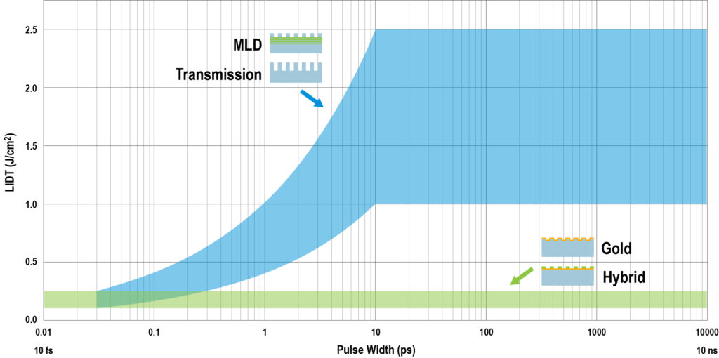
To a reasonable approximation, the LIDT of gold gratings does not depend significantly on the pulse width. The LIDT is typically ~ 100 to several hundred mJ/cm2, even for pulses as short as 10’s of fs. The damage threshold for all-dielectric MLD and transmission gratings also exhibits little dependence on pulse width for pulses longer than ~ 10 ps, where it is typically several J/cm2. Transmission grating LIDT values may be even higher, though for simplicity we don’t show a different range here. For shorter pulses, the LIDT decreases with the pulse width, and has been shown to be comparable to that of gold gratings for pulses of several 10’s of fs width. The exact dependence is not fully understood nor agreed upon, though it is usually modeled as a power law. Because hybrid gratings are so new and not very thoroughly studied, the LIDT performance is not well known. For 10’s of fs pulses hybrid grating LIDT values have been shown to be comparable to or perhaps slightly higher than those of gold gratings. They might even be higher than gold grating values for longer pulses, but since there is no data to confirm this possibility, here we assume they are comparable to the gold grating LIDT for all pulse widths.
For a given LIDT value, the grating size is usually determined by the final pulse energy – the higher the energy the larger the gratings required. For example, if the final, compressed pulse is 1 ps wide and has an energy of 100 J, the beam area should be at least 200 cm2 for an MLD grating (assuming LIDT = 0.5 J/cm2) and 1,000 cm2 for a gold grating (assuming LIDT = 0.1 J/cm2).
Alternatively, for very high pulse energies, the maximum grating size might limit the highest achievable pulse energy. Fig. 3 shows approximate possible sizes for the major grating types, based on PGL’s current manufacturing processes.
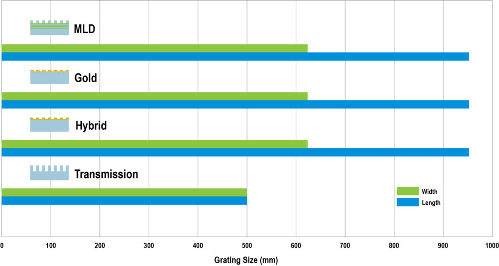
As an example, the maximum beam size possible today is just over 600 mm, corresponding to ~ 3,600 cm2, so the maximum pulse energy using gold gratings is about 700 J, and using MLD gratings it is about 7 kJ.
Since many of the fabrication processes are shared by the different grating types, the size limitations are similar. The notable exception is transmission gratings, which require deeper, more challenging etching and therefore utilize a different process which currently has a more restricted size range. All of PGL’s manufacturing processes are fundamentally scalable in size, and it is likely that in the future higher pulse energy requirements will drive an expansion of maximum grating size.
Dispersion:
An important design parameter for CPA lasers is the pulse stretch factor, or the ratio of the stretched pulse width to the compressed pulse width. This factor is determined by the maximum possible amplifier intensity, beyond which saturation or damage occurs. The initial (or compressed) pulse width and the stretch factor in turn dictate how much temporal dispersion is required for the stretcher and compressor. As explained in detail in [1,2], the temporal dispersion of a 4-grating compressor is determined by the wavelength, angle of incidence, and grating period or line density. The dependence of temporal dispersion dτ/dλ (ps/nm) on these parameters can be summarized by the equation
 (1)
(1)
where s is the separation between each pair of parallel gratings in the compressor, measured in the direction perpendicular to the grating surface (in mm), λ is the wavelength (in nm), and Δ is a Temporal Dispersion Factor which has units of ps/mm. According to Eq. (1) in [1], Δ is given by
 (2)
(2)
where m is the order of diffraction (usually –1), f is the grating line density or frequency (in lines/mm), c is the speed of light, and θm is the angle of diffraction. The factor of 2 is included so that Eq. (1) accounts for all four grating bounces. Note that Δ depends only on the product of the wavelength and grating frequency, or, equivalently, wavelength-to-grating-period ratio. Fig. 4 shows the dependence of Δ on the wavelength-to-grating-period ratio, each value of which corresponds to a unique Littrow angle (shown on the top axis).
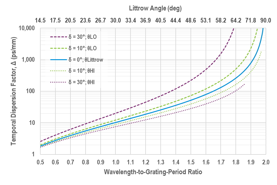
In Fig. 4 the solid blue line shows the temporal dispersion factor when light is incident on the grating at the Littrow angle. The temporal dispersion can be adjusted by changing the angle of incidence. The other lines on this graph show the temporal dispersion when light is incident at angles below the Littrow angle which correspond to a deviation between incident and diffracted beams of 10° and 30° (designated θLO), and when light is incident at angles above the Littrow angle corresponding to these same beam deviation values (designated θHI).
As an example, consider an 800 nm laser compressed by 1480 lines/mm gratings, so that the wavelength-to-period ratio is about 1.18 (800 nm x 1480 lines/mm x 10–6 mm/nm). Assuming a 30° beam deviation, if the light is incident at the low angle (22.8°), the temporal dispersion factor is Δ = 12 ps/mm, whereas light incident at the high angle (52.8°) yields a factor of Δ = 42 ps/mm. Suppose the pulse width is 30 fs, which corresponds to a spectral bandwidth of 31 nm, and amplifier considerations require a stretch factor of 10,000. To compress this 300 ps pulse requires 9.7 ps/nm of temporal dispersion. Using Eq. (1), light incident on the compressor at 22.8° requires a grating separation of 650 mm, whereas light incident 52.8° requires a separation of 185 mm.
Other system considerations:
Once the wavelength, damage, and dispersion requirements have all been considered, as discussed above, it is likely there still remain many options for choosing diffraction grating type. Narrowing the choice down further now depends on all other system considerations, such as: the loss budget, which drives how high the diffraction efficiency must be, the spectral bandwidth of the pulse, and any system layout and geometry considerations.
As an example of the last, the ratio of the beam size (driven by LIDT) to the grating separation (driven by dispersion) determines the smallest possible beam deviation angle for a reflection grating. Some grating types perform best at or very close to the Littrow angle, and therefore require a very small beam deviation angle, while others operate best only with very large deviation angles, and still others can operate in either regime.
To help steer designers of pulse compressors through these many system-driven factors, PGL has developed the grating design guide shown in Fig. 5. This guide considers three main performance criteria—diffraction efficiency, spectral bandwidth, and angular bandwidth—for each of the four main grating types: MLD, gold, hybrid metal-dielectric, and transmission gratings. Realizable grating designs are classified for these three performance criteria in a “good, better, best” format, showing the dependence on the wavelength-to-grating-period ratio (and hence Littrow angle) and on polarization.
For each grating type, there are no realizable designs for a wavelength-to-grating-period ratio (or, equivalently, a wavelength-grating-frequency product) greater than 2.0 because diffraction cannot occur at any angle for this case. Furthermore, designs for a ratio below about 0.7 are also not included because higher diffraction orders occur in this regime and hence it is not possible to create designs with very high efficiency into a single order. For other combinations of polarization and wavelength-period ratio the grating grooves are simply too deep and/or the duty cycle is too high or low to manufacture the gratings accurately and with good yield.
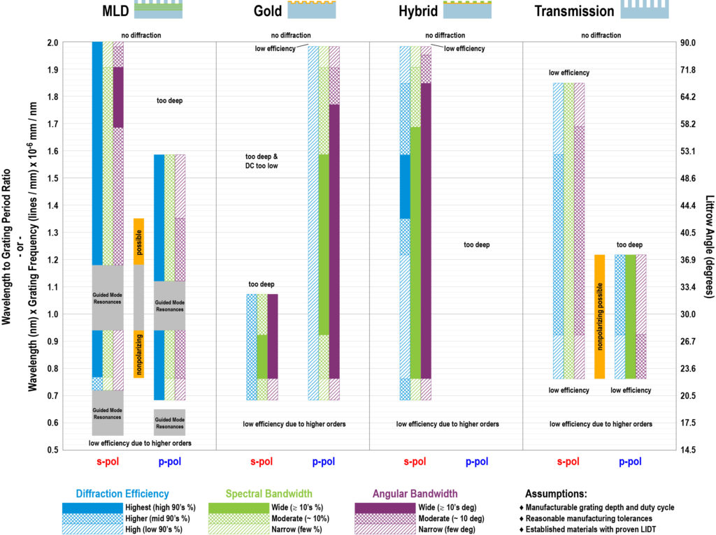
From this guide it is evident why MLD gratings tend to be designed with a wavelength-period ratio of about 1.8 (Littrow angle about 65°), since all three performance criteria are strong there. But note that MLD gratings never achieve the very wide (10’s of %) bandwidth that gold and hybrid gratings can achieve.
The grayed-out areas in the MLD section correspond to regions where so-called guided-mode resonances (GMRs) occur and interfere with normal grating operation. These features, which manifest as sharp dips or peaks in the efficiency spectrum, arise due to resonant coupling between higher diffraction orders (generally –2 and +1) and modes guided in the direction parallel to the grating surface and perpendicular to the grating lines by the higher-index layers in the thin-film stack below the grating region. In addition to affecting the spectrum, they can cause very high localized intensity values which may lower the LIDT.
Only hybrid gratings have an operating regime where all three performance criteria are at their best (for a wavelength-period ratio of about 1.5 or Littrow angle of about 45 – 50°). Only MLD and transmission gratings can achieve nonpolarizing operation, or designs where there is good performance for both s- and p-polarizations simultaneously.
As noted above, this guide makes certain manufacturability and material assumptions. Grating designs that do not follow these assumptions are sometimes possible, and PGL’s expert design and manufacturing engineers are able to assess what is feasible in such cases.
References:
[1] See PGL Technical Notes, “Temporal Dispersion.”
[2] See PGL Technical Notes, “Dispersion and Pulses.”
5 Commerce Way, Carver, MA 02330, USA|+1.508.503.1719|sales@plymouthgrating.com